Page 492 of 1202
EM0JQ-06
EM9411
EM9412
P20480
SST
P20478
SST
P20477
12 mm
Hexagon
Wrench EM-70
- ENGINE MECHANICALCYLINDER BLOCK
1996 TERCEL (RM440U)
DISASSEMBLY
1. M/T:
REMOVE CLUTCH COVER AND DISC
2. REMOVE FLYWHEEL (M/T) OR DRIVE PLATE (A/T)
3. REMOVE REAR END PLATE
4. INSTALL ENGINE TO ENGINE STAND FOR DIS-
ASSEMBLY
5. REMOVE TIMING BELT AND PULLEYS
6. REMOVE CYLINDER HEAD
7. REMOVE OIL DIPSTICK GUIDE AND GENERATOR
ADJUSTING BAR
8. REMOVE WATER PUMP WITH WATER INLET PIPE
9. REMOVE GENERATOR BRACKET
10. REMOVE KNOCK SENSOR
Using SST, remove the knock sensor.
SST 09816-30010
11. REMOVE RH ENGINE MOUNTING BRACKET
12. REMOVE OIL FILTER
13. REMOVE OIL PRESSURE SWITCH
Using SST, remove the oil pressure switch.
SST 09816-30010
14. REMOVE OIL PUMP AND PRESSURE REGULATOR
VA LV E
15. REMOVE OIL FILTER UNION
Using a 12 mm hexagon wrench, remove the oil filter union.
Page 500 of 1202
P00393
EM0JR-04
Z07983
P00390
EM9429
Front
Cylinder Bore Size Mark (1,2 or 3) EM-78
- ENGINE MECHANICALCYLINDER BLOCK
1996 TERCEL (RM440U)
INSPECTION
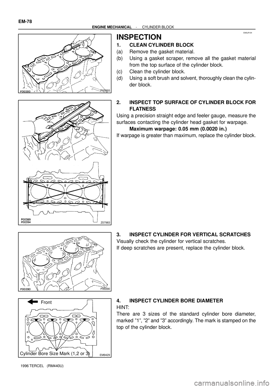
1. CLEAN CYLINDER BLOCK
(a) Remove the gasket material.
(b) Using a gasket scraper, remove all the gasket material
from the top surface of the cylinder block.
(c) Clean the cylinder block.
(d) Using a soft brush and solvent, thoroughly clean the cylin-
der block.
2. INSPECT TOP SURFACE OF CYLINDER BLOCK FOR
FLATNESS
Using a precision straight edge and feeler gauge, measure the
surfaces contacting the cylinder head gasket for warpage.
Maximum warpage: 0.05 mm (0.0020 in.)
If warpage is greater than maximum, replace the cylinder block.
3. INSPECT CYLINDER FOR VERTICAL SCRATCHES
Visually check the cylinder for vertical scratches.
If deep scratches are present, replace the cylinder block.
4. INSPECT CYLINDER BORE DIAMETER
HINT:
There are 3 sizes of the standard cylinder bore diameter,
marked º1º, º2º and º3º accordingly. The mark is stamped on the
top of the cylinder block.
Page 502 of 1202
P20539
P20561
Mark 1, 2 or 3
Front mark (Cavity)
P20474
23 mm
(0.91 in.)
P20571
Mark 1, 2 or 3
Front
Front mark (Cavity)Mark 1, 2 or 3 EM-80
- ENGINE MECHANICALCYLINDER BLOCK
1996 TERCEL (RM440U)
(c) Using a soft brush and solvent, thoroughly clean the pis-
ton.
NOTICE:
Do not damage the piston.
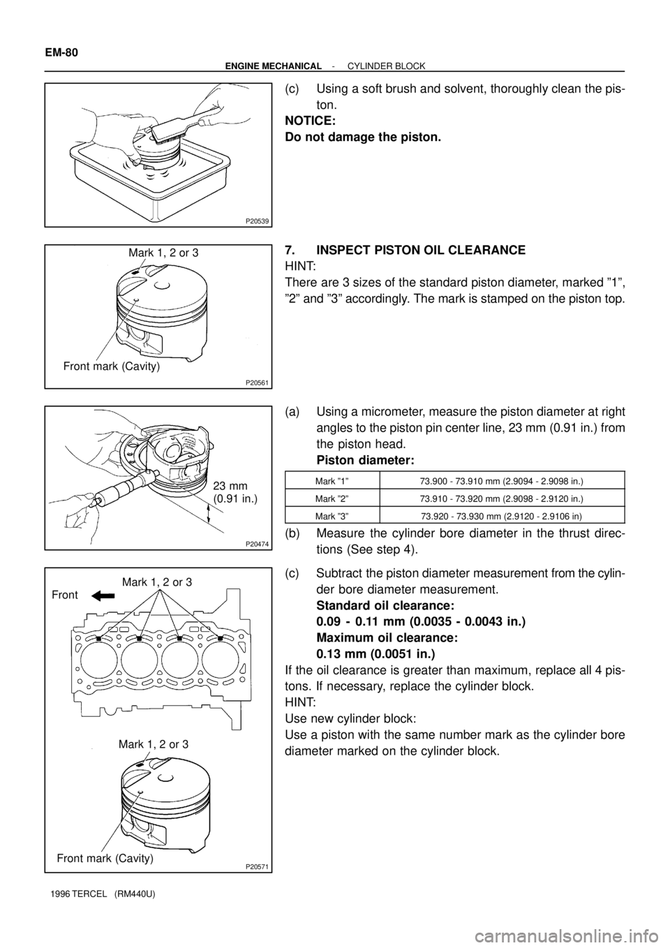
7. INSPECT PISTON OIL CLEARANCE
HINT:
There are 3 sizes of the standard piston diameter, marked º1º,
º2º and º3º accordingly. The mark is stamped on the piston top.
(a) Using a micrometer, measure the piston diameter at right
angles to the piston pin center line, 23 mm (0.91 in.) from
the piston head.
Piston diameter:
Mark º1º73.900 - 73.910 mm (2.9094 - 2.9098 in.)
Mark º2º73.910 - 73.920 mm (2.9098 - 2.9120 in.)
Mark º3º73.920 - 73.930 mm (2.9120 - 2.9106 in)
(b) Measure the cylinder bore diameter in the thrust direc-
tions (See step 4).
(c) Subtract the piston diameter measurement from the cylin-
der bore diameter measurement.
Standard oil clearance:
0.09 - 0.11 mm (0.0035 - 0.0043 in.)
Maximum oil clearance:
0.13 mm (0.0051 in.)
If the oil clearance is greater than maximum, replace all 4 pis-
tons. If necessary, replace the cylinder block.
HINT:
Use new cylinder block:
Use a piston with the same number mark as the cylinder bore
diameter marked on the cylinder block.
Page 509 of 1202
P20551
P20530
Front
Z14291
1
2 3
45
6
7
89
10
EM3480
P20569
Front Mark
(Cavity)
FrontPush
- ENGINE MECHANICALCYLINDER BLOCK
EM-87
1996 TERCEL (RM440U)
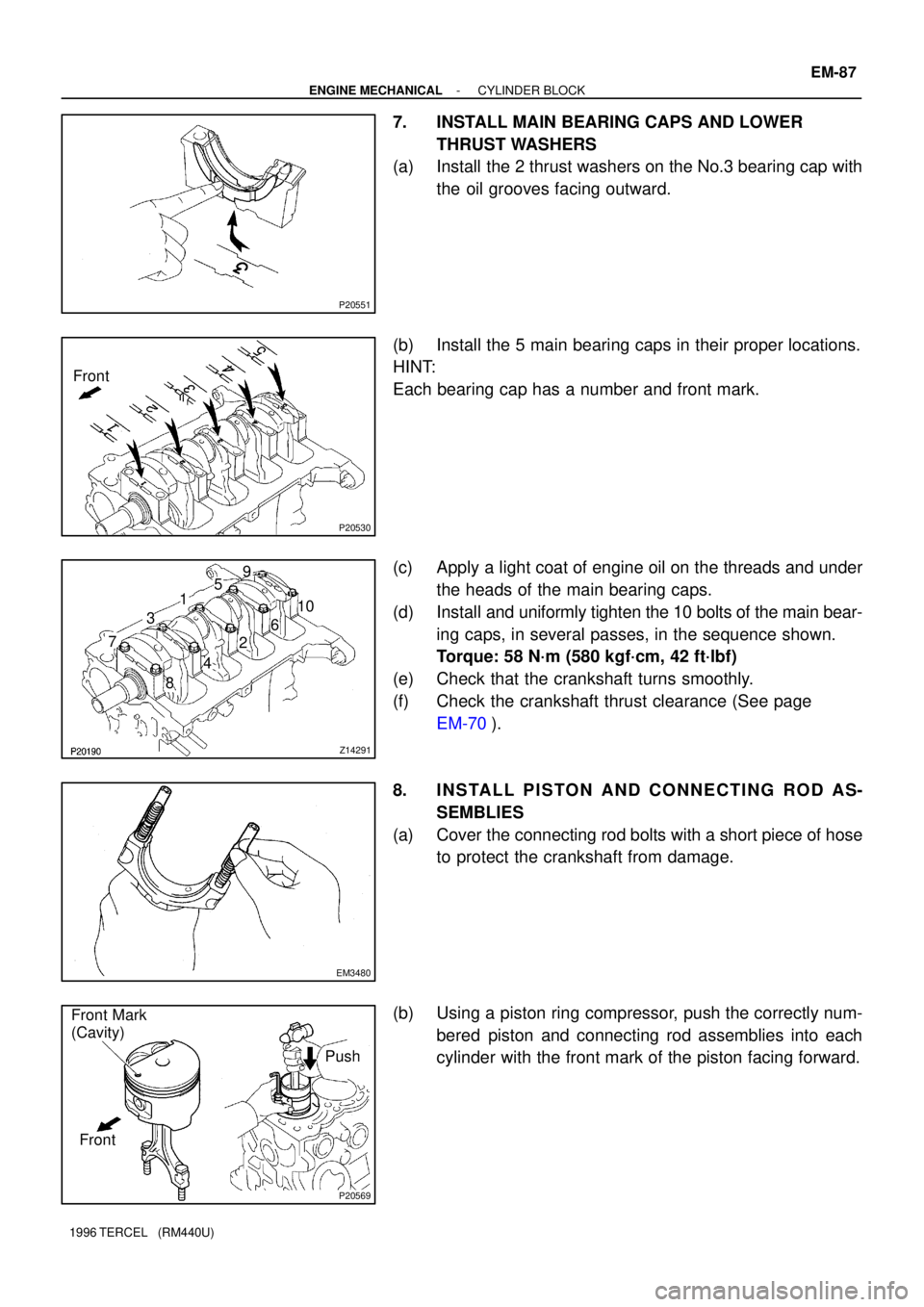
7. INSTALL MAIN BEARING CAPS AND LOWER
THRUST WASHERS
(a) Install the 2 thrust washers on the No.3 bearing cap with
the oil grooves facing outward.
(b) Install the 5 main bearing caps in their proper locations.
HINT:
Each bearing cap has a number and front mark.
(c) Apply a light coat of engine oil on the threads and under
the heads of the main bearing caps.
(d) Install and uniformly tighten the 10 bolts of the main bear-
ing caps, in several passes, in the sequence shown.
Torque: 58 N´m (580 kgf´cm, 42 ft´lbf)
(e) Check that the crankshaft turns smoothly.
(f) Check the crankshaft thrust clearance (See page
EM-70).
8. INSTALL PISTON AND CONNECTING ROD AS-
SEMBLIES
(a) Cover the connecting rod bolts with a short piece of hose
to protect the crankshaft from damage.
(b) Using a piston ring compressor, push the correctly num-
bered piston and connecting rod assemblies into each
cylinder with the front mark of the piston facing forward.
Page 512 of 1202
P20750
P20480
SST
P20545
EM9412
EM7333
EM-90
- ENGINE MECHANICALCYLINDER BLOCK
1996 TERCEL (RM440U)
15. INSTALL RH ENGINE MOUNTING BRACKET
Torque: 58 N´m (590 kgf´cm, 43 ft´lbf)
16. INSTALL KNOCK SENSOR
Using SST, install the knock sensor.
SST 09816-30010
Torque: 45 N´m (450 kgf´cm, 33 ft´lbf)
17. INSTALL GENERATOR BRACKET
Torque: 24 N´m (240 kgf´cm, 18 ft´lbf)
18. INSTALL WATER PUMP WITH WATER INLET PIPE
19. INSTALL OIL DIPSTICK GUIDE AND GENERATOR AD-
JUSTING BAR
20. INSTALL CYLINDER HEAD
21. INSTALL TIMING BELT AND PULLEYS
22. REMOVE ENGINE STAND
23. INSTALL REAR END PLATE
Torque: 10 N´m (100 kgf´cm, 7 ft´lbf)
24. M/T:
INSTALL FLYWHEEL
(a) Apply adhesive to 2 or 3 threads of new mounting bolt
end.
Adhesive:
Part No. 08833-00070, THREE BOND 1324 or
equivalent
Page 518 of 1202
EC1228
Cylinder Head Side
Clean Hose
EC07D-03
EC1229
Intake Manifold Side
Clean Hose
EC3648
EC-4- EMISSION CONTROLPOSITIVE CRANKCASE VENTILATION (PCV)
SYSTEM
517 Author�: Date�:
1996 TERCEL (RM440U)
POSITIVE CRANKCASE
VENTILATION (PCV) SYSTEM
INSPECTION
1. REMOVE PCV VALVE
2. ATTACH CLEAN HOSE TO PCV VALVE
3. BLOW AIR FROM CYLINDER HEAD SIDE
Check that air passes through easily.
NOTICE:
�Do not suck air through the valve.
�Petroleum substances inside the valve are harmful.
4. BLOW AIR FROM INTAKE MANIFOLD SIDE
Check that air passes through with difficulty.
If the PCV valve fails either of the checks, replace it.
5. REINSTALL PCV VALVE
6. VISUALLY INSPECT HOSES, CONNECTIONS AND
GASKETS
Check for cracks, leaks or damage.
Page 526 of 1202
SF1PQ-02
- MFIMFI SYSTEM
MF-1
525 Author�: Date�:
1996 TERCEL (RM440U)
MFI SYSTEM
PRECAUTION
1. BEFORE WORKING ON FUEL SYSTEM, DISCON-
NECT NEGATIVE (-) TERMINAL CABLE FROM BAT-
TERY
HINT:
Any diagnostic trouble code retained by the computer will be
erased when the negative (-) terminal cable is disconnected.
Therefore, if necessary, read the diagnosis before disconnect-
ing the negative (-) terminal cable from the battery.
2. DO NOT SMOKE OR WORK NEAR AN OPEN FLAME
WHEN WORKING ON THE FUEL SYSTEM
3. KEEP GASOLINE AWAY FROM RUBBER OR LEATH-
ER PARTS
4. MAINTENANCE PRECAUTIONS
(a) In event of engine misfire, the following precautions
should be taken.
(1) Check proper connection to battery terminals, etc.
(2) Handle higt-tension cords carefully.
(3) After repair work, check that the ignition coil termi-
nals and all other ignition system lines are recon-
nected securely.
(4) When cleaning the engine compartment, be espe-
cially careful to protect the electrical system from
water.
(b) Precautions when handling the oxygen sensor.
(1) Do not allow the oxygen sensor to drop or hit
against an object.
(2) Do not allow the sensor to come into contact with
water.
5. IF VEHICLE IS EQUIPPED WITH MOBILE RADIO SYS-
TEM (HAM, CB, ETC.)
If the vehicle is equipped with a mobile communication system,
refer to the precaution in the IN section.
6. AIR INDUCTION SYSTEM
(a) Separation of the engine oil dipstick, oil filler cap, PCV
hose, etc. may cause the engine out of tune.
(b) Disconnection, looseness or cracks in the parts of the air
induction system between the throttle body and cylinder
head will cause air suction and cause the engine out of
tune.
7. ELECTRONIC CONTROL SYSTEM
(a) Before removing MFI wiring connectors, terminals, etc.,
first disconnect the power by either turning the ignition
switch to LOCK or disconnecting the negative (-) terminal
cable from the battery.
Page 528 of 1202
P20175
New
Gasket
FI1654
Fulcrum Length
SST
30 cm
FI4295
CORRECT
WRONG
WRONG Delivery Pipe O-Ring
Grommet
Injector
FI4296
Delivery
Pipe
O-Ring
Grommet
InjectorCylinder Head
- MFIMFI SYSTEM
MF-3
527 Author�: Date�:
1996 TERCEL (RM440U)
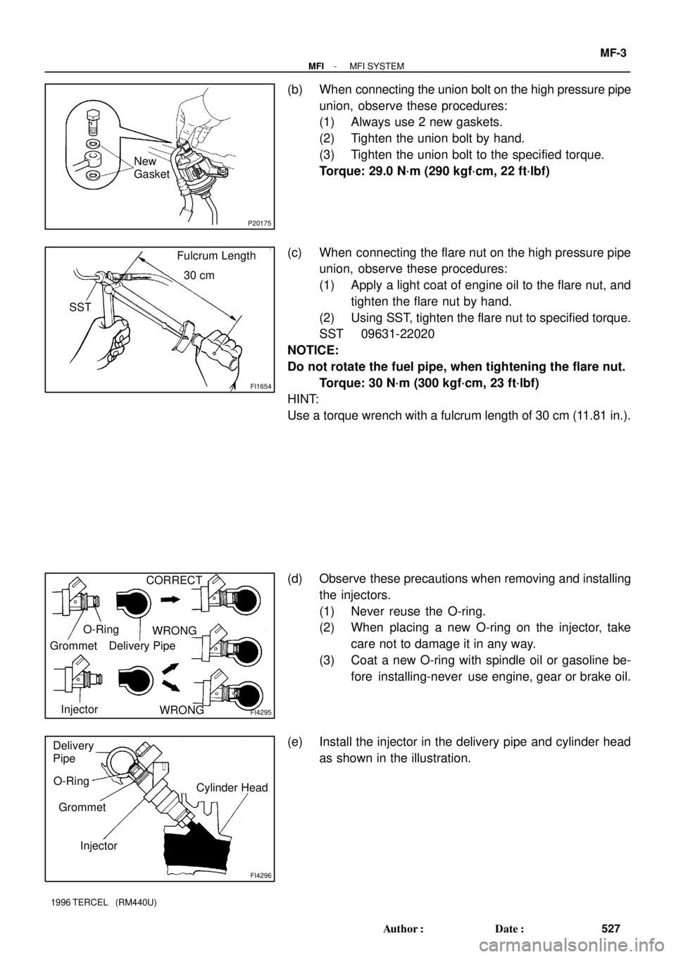
(b) When connecting the union bolt on the high pressure pipe
union, observe these procedures:
(1) Always use 2 new gaskets.
(2) Tighten the union bolt by hand.
(3) Tighten the union bolt to the specified torque.
Torque: 29.0 N´m (290 kgf´cm, 22 ft´lbf)
(c) When connecting the flare nut on the high pressure pipe
union, observe these procedures:
(1) Apply a light coat of engine oil to the flare nut, and
tighten the flare nut by hand.
(2) Using SST, tighten the flare nut to specified torque.
SST 09631-22020
NOTICE:
Do not rotate the fuel pipe, when tightening the flare nut.
Torque: 30 N´m (300 kgf´cm, 23 ft´lbf)
HINT:
Use a torque wrench with a fulcrum length of 30 cm (11.81 in.).
(d) Observe these precautions when removing and installing
the injectors.
(1) Never reuse the O-ring.
(2) When placing a new O-ring on the injector, take
care not to damage it in any way.
(3) Coat a new O-ring with spindle oil or gasoline be-
fore installing-never use engine, gear or brake oil.
(e) Install the injector in the delivery pipe and cylinder head
as shown in the illustration.