Page 21 of 1202

B02389
B02390
HEAT METHOD: When the problem seems to occur when the suspect area is heated. 2
NOTICE:3 WATER SPRINKLING METHOD:
(1)
(2)
4 OTHER: When a malfunction seems to occur when electrical load is excessive.When the malfunction seems to occur on a rainy day or in a
high-humidity condition. Heat the component that is the likely cause of the malfunction
with a hair dryer or similar object. Check to see if the malfunction
occurs.
Sprinkle water onto the vehicle and check to see if the malfunc-
tion occurs.
Turn on all electrical loads including the heater blower, head
lights, rear window defogger, etc. and check to see if the mal-
function occurs.ON HINT:
If a vehicle is subject to water leakage, the leaked water may
contaminate the ECU. When testing a vehicle with a water leak-
age problem, special caution must be taken.
Malfunc-
tion
Do not heat to more than 60°C (140°F). (Temperature
is limited not to damage the components.)
Do not apply heat directly to parts in the ECU. (1)
(2)
Never sprinkle water directly into the engine compart-
ment, but indirectly change the temperature and hu-
midity by applying water spray onto the radiator front
surface.
Never apply water directly onto the electronic compo-
nents. NOTICE:
- INTRODUCTIONHOW TO TROUBLESHOOT ECU CONTROLLED
SYSTEMSIN-21
1996 TERCEL (RM440U)
Page 353 of 1202

R05894 AB0117
H00001
Airbag Sensor
Assembly LOCK
Spiral
Cable D SquibP Squib
R14285 AB0119H00021
ON
Airbag Sensor Assembly
ACC
IG2
(+) (-)
DI-178
- DIAGNOSTICSSUPPLEMENTAL RESTRAINT SYSTEM
1996 TERCEL (RM440U)
INSPECTION PROCEDURE
1 Preparation.
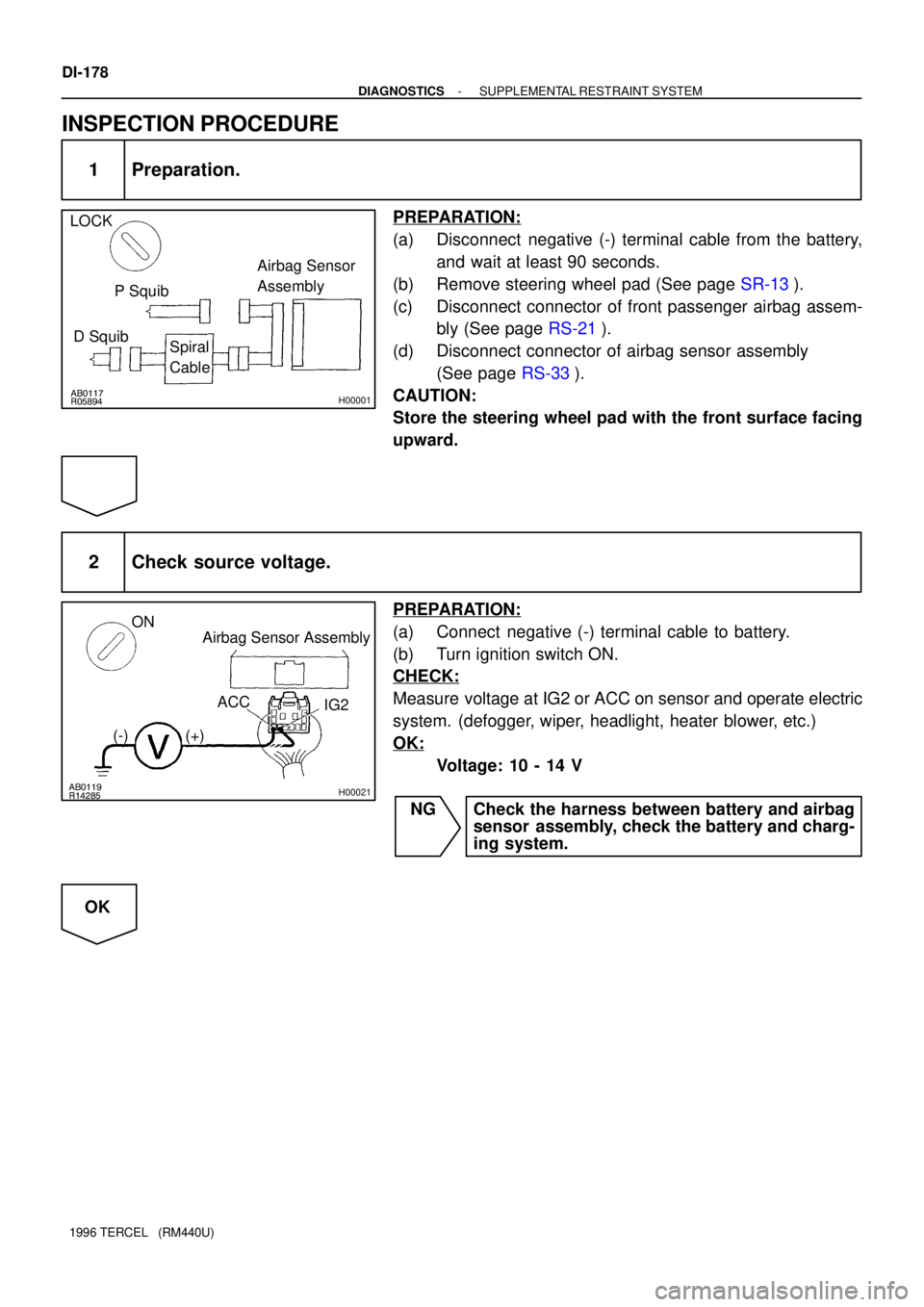
PREPARATION:
(a) Disconnect negative (-) terminal cable from the battery,
and wait at least 90 seconds.
(b) Remove steering wheel pad (See page SR-13).
(c) Disconnect connector of front passenger airbag assem-
bly (See page RS-21).
(d) Disconnect connector of airbag sensor assembly
(See page RS-33).
CAUTION:
Store the steering wheel pad with the front surface facing
upward.
2 Check source voltage.
PREPARATION:
(a) Connect negative (-) terminal cable to battery.
(b) Turn ignition switch ON.
CHECK:
Measure voltage at IG2 or ACC on sensor and operate electric
system. (defogger, wiper, headlight, heater blower, etc.)
OK:
Voltage: 10 - 14 V
NG Check the harness between battery and airbag
sensor assembly, check the battery and charg-
ing system.
OK
Page 354 of 1202
H00003
ON
- DIAGNOSTICSSUPPLEMENTAL RESTRAINT SYSTEM
DI-179
1996 TERCEL (RM440U)
3 Does SRS warning light turn off?
PREPARATION:
(a) Turn ignition switch to LOCK.
(b) Connect steering wheel pad connector.
(c) Connect front passenger airbag assembly connector.
(d) Connect airbag sensor assembly connector.
(e) Turn ignition switch ON.
CHECK:
Operate electric system checked in defogger, wiper, headlight,
heater blower, etc. and check that SRS warning light goes off.
NO Check for DTCs. If a DTC is output, perform trou-
bleshooting for the DTC. If a normal code is out-
put, replace airbag sensor assembly.
YES
From the results of the above inspection, the malfunctioning part can now be considered normal.
To make sure of this, use the simulation method to check.
Page 1009 of 1202

BE-8
- BODY ELECTRICALBODY ELECTRICAL SYSTEM
1996 TERCEL (RM440U)
DEFOGGER SYSTEM
TroubleParts nameSee page
Rear window defogger does not operate.
(w/Timer)
1. DEF M-Fuse (I/P J/B)
2. GAUGE Fuse (I/P J/B)
3. Defogger Switch
4. Defogger Relay
5. Defogger Wire
6. Wire Harness-
-
BE-46
BE-46
BE-46
-
Rear window defogger does not operate.
(w/o Timer)
1. DEF M-Fuse (I/P J/B)
2. Defogger Switch
3. Defogger Wire
4. Wire Harness-
BE-46
BE-46
-
POWER WINDOW CONTROL SYSTEM
TroubleParts nameSee page
Power window does not operate.
(Door lock does not operate.)1. POWER M-Fuse (R/B No.7)
2. Wire Harness-
-
Power window does not operate.
(Door lock is normal.)
1. GAUGE Fuse (I/P J/B)
2. Ignition Switch
3. POWER M-Fuse (R/B No.7)
4. Power Main Relay (R/B No.7)
5. Power Window Master Switch
6. Wire Harness-
BE-1 1
-
BE-49
BE-49
-
ºOne Touch Power Window Systemº does not operate.1. Power Window Master SwitchBE-49
Only one window glass does not move.
1. Power Window Master Switch
2. Power Window Switch
3. Power Window Motor
4. Wire HarnessBE-49
BE-49
BE-49
-
ºWindow Lock Systemº does not operate.1. Power Window Master SwitchBE-49
ºWindow Lock Illuminationº does not light up.1. Power Window Master SwitchBE-49
Page 1047 of 1202

BE26S-01
Z14866
Relay Side
1
2
3 4 5 6
Z14867
2
3
6
ON
Z08467
Wire Harness Side
Z14868
ON BE-46
- BODY ELECTRICALDEFOGGER SYSTEM
1996 TERCEL (RM440U)
INSPECTION
1. w/ Timer:
INSPECT DEFOGGER SWITCH CONTINUITY
Check that there is continuity between terminals 1 and 3.
If continuity is not as specified, check the bulb.
2. INSPECT DEFOGGER TIMER OPERATION
(a) Connect the positive (+) lead from the battery to terminal
2 and the negative (-) lead to terminal 4.
(b) Connect the positive (+) lead from the battery to terminal
6 through a 3.4 W tester bulb.
(c) Push the defogger switch ON, check that the indicator
light and test bulb light up for 12 to 18 minutes, then the
indicator light and test bulb lights go out.
If operation is not as specified, replace the switch.
3. INSPECT DEFOGGER TIMER CIRCUIT
Disconnect the connector from the switch and inspect the con-
nector on the wire harness side, as shown in the chart.
Tester connectionConditionSpecified condition
4 - GroundConstantContinuity
2 - GroundIgnition switch LOCK or ACCNo voltage
2 - GroundIgnition switch ONBattery positive voltage
6 - GroundIgnition switch LOCK or ACCNo voltage
6 - GroundIgnition switch ONBattery positive voltage
-Connect terminals 4 and 6.Defogger system operation is normal
If the circuit is not as specified, replace the switch.
4. w/o Timer:
INSPECT DEFOGGER SWITCH CONTINUITY
ConditionTester connectionSpecified condition
Switch OFF2 - 6No continuity
Switch ON2 - 4 - 6Continuity
Illumination circuit1 - 3Continuity
If continuity is not as specified, replace the switch.
Page 1114 of 1202
BO345-01
N12301
- BODYBACK WINDOW GLASS
BO-43
1996 TERCEL (RM440U)
REMOVAL
1. DISCONNECT DEFOGGER CONNECTOR
2. REMOVE REAR SEAT CUSHION AND SEATBACK
3. REMOVE REAR SEAT BELT
4. REMOVE FRONT DOOR SCUFF PLATE
5. REMOVE QUARTER TRIM BOARD
6. REMOVE FRONT SEAT BELT
7. REMOVE HIGH MOUNTED STOP LIGHT
8. REMOVE PACKAGE TRAY GARNISH
9. REMOVE BACK WINDOW MOULDING
Using a knife, cut off the body.
NOTICE:
Do not damage the body with the knife.
10. REMOVE BACK WINDOW GLASS
Remove the glass in the same manner as windshield (See page
BO-34).
Page 1115 of 1202

BO346-01
N12302
BO-44
- BODYBACK WINDOW GLASS
1996 TERCEL (RM440U)
INSTALLATION
1. CLEAN AND SHAPE CONTACT SURFACE OF BODY
(See page BO-35)
2. CLEAN REMOVED GLASS (See page BO-35)
3. POSITION GLASS (See page BO-35)
4. CLEAN CONTACT SURFACE GLASS (See page
BO-35)
5. COAT CONTACT SURFACE OF BODY WITH PRIMER
ºMº (See page BO-35)
6. COAT CONTACT SURFACE OF GLASS WITH PRIMER
ºGº (See page BO-35)
7. MIX ADHESIVE COATING (See page BO-35)
8. APPLY ADHESIVE (See page BO-35)
9. INSTALL GLASS (See page BO-35)
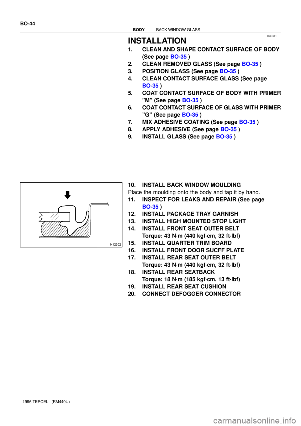
10. INSTALL BACK WINDOW MOULDING
Place the moulding onto the body and tap it by hand.
11. INSPECT FOR LEAKS AND REPAIR (See page
BO-35)
12. INSTALL PACKAGE TRAY GARNISH
13. INSTALL HIGH MOUNTED STOP LIGHT
14. INSTALL FRONT SEAT OUTER BELT
Torque: 43 N´m (440 kgf´cm, 32 ft´lbf)
15. INSTALL QUARTER TRIM BOARD
16. INSTALL FRONT DOOR SUCFF PLATE
17. INSTALL REAR SEAT OUTER BELT
Torque: 43 N´m (440 kgf´cm, 32 ft´lbf)
18. INSTALL REAR SEATBACK
Torque: 18 N´m (185 kgf´cm, 13 ft´lbf)
19. INSTALL REAR SEAT CUSHION
20. CONNECT DEFOGGER CONNECTOR