Page 720 of 1202
MX07Z-04
Z18913
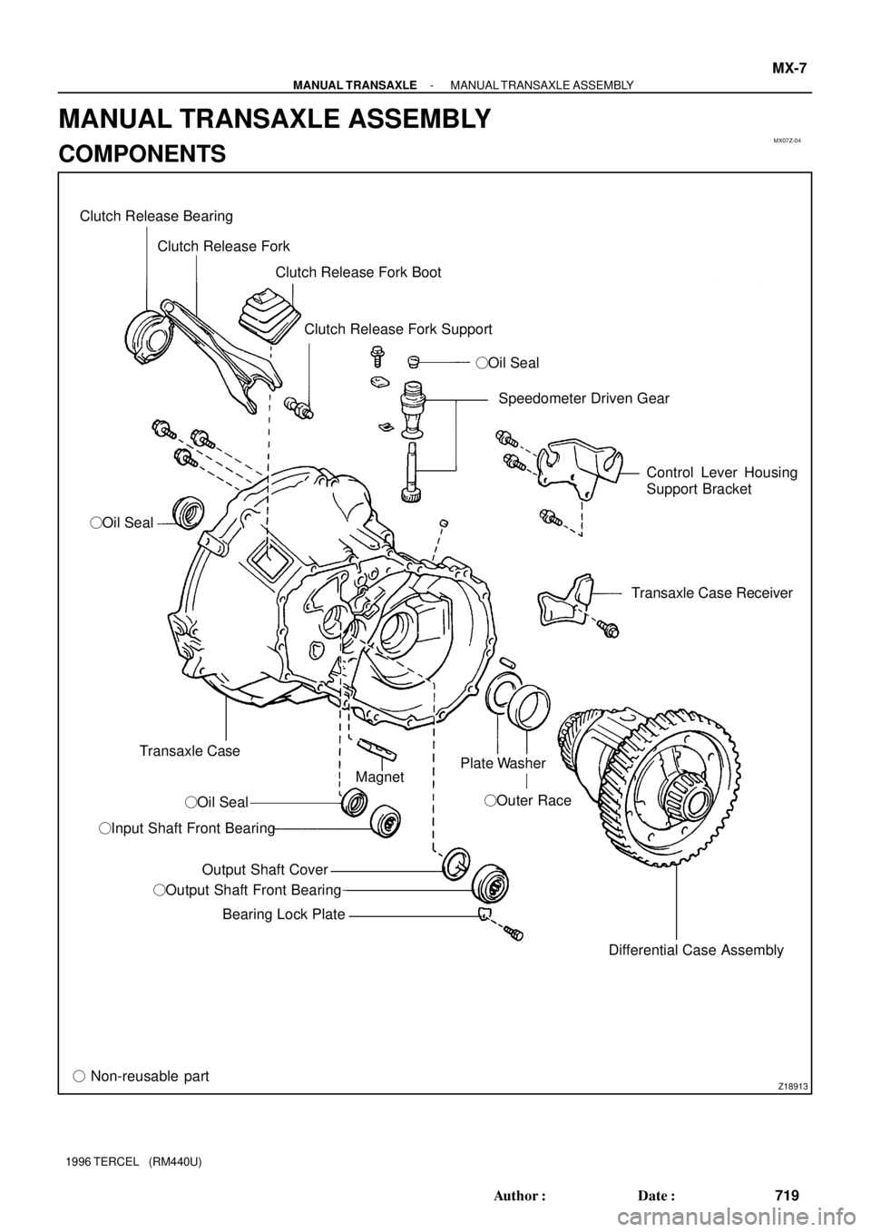
Clutch Release Bearing
Clutch Release Fork
Clutch Release Fork Boot
Clutch Release Fork Support
�Oil Seal
�Oil Seal
Transaxle Case
�Oil Seal
�Input Shaft Front Bearing
Output Shaft Cover
�Output Shaft Front Bearing
Bearing Lock Plate
� Non-reusable partSpeedometer Driven Gear
Control Lever Housing
Support Bracket
Transaxle Case Receiver
Differential Case Assembly �Outer Race Magnet
Plate Washer
- MANUAL TRANSAXLEMANUAL TRANSAXLE ASSEMBLY
MX-7
719 Author�: Date�:
1996 TERCEL (RM440U)
MANUAL TRANSAXLE ASSEMBLY
COMPONENTS
Page 728 of 1202
N00047
CM0141
- MANUAL TRANSAXLEMANUAL TRANSAXLE ASSEMBLY
MX-15
1996 TERCEL (RM440U)
(e) C151:
Using a magnetic finger, remove the 2 balls from the re-
verse shift fork.
(f) Remove the No.3 shift fork shaft and reverse shift fork.
(g) Pull out the No.1 shift fork shaft.
(h) Remove the No.1 and No.2 shift forks.
24. REMOVE INPUT AND OUTPUT SHAFTS TOGETHER
FROM TRANSAXLE CASE
25. REMOVE DIFFERENTIAL CASE ASSEMBLY
HINT:
Before reassembly, inspect the differential side bearing pre-
load.
26. REMOVE MAGNET FROM TRANSAXLE CASE
27. REMOVE NO.3 HUB SLEEVE, SHIFTING KEY AND
SPRING FROM NO.3 CLUTCH HUB
Using a screwdriver, remove the 3 shifting keys and 2 springs
from the No.3 clutch hub.
Page 748 of 1202
MX07U-03
Q06511
�Oil Seal
Plate Washer
�Outer Race and Side Bearing
Speedometer Drive Gear
Straight Pin
�Side Bearing and Outer Race
�Oil Seal
Ring Gear Plate Washer Differential Case Pinion Shaft
Pinion Gear
Thrust Washer
Side Gear
Thrust Washer
� Non-reusable partx6
- MANUAL TRANSAXLEDIFFERENTIAL CASE
MX-35
747 Author�: Date�:
1996 TERCEL (RM440U)
DIFFERENTIAL CASE
COMPONENTS
Page 749 of 1202

DISASSEMBLY
1. REMOVE SIDE BEARING FROM DIFFERENTIAL
CASE
(a) Using SST,")
MX07V-03
Z16129
SST
MT0081
Matchmarks
MT0083
MT0084
N00098
SST MX-36
- MANUAL TRANSAXLEDIFFERENTIAL CASE
1996 TERCEL (RM440U)
DISASSEMBLY
1. REMOVE SIDE BEARING FROM DIFFERENTIAL
CASE
(a) Using SST, remove the bearings from both sides of the
case.
SST 09950- 00020, 09950- 00030, 09950- 60010
(09951-00360)
(b) Remove the speedometer drive gear from the RH side.
2. REMOVE RING GEAR
(a) Place matchmarks on the ring gear and case.
(b) Remove the 6 bolts.
(c) Using a plastic hammer, remove the ring gear from the
case.
3. INSPECT SIDE GEAR BACKLASH
Using a dial indicator, measure the backlash of one side gear
while holding one pinion toward the case.
Standard backlash:
0.05 - 0.20 mm (0.0020 - 0.0079 in.)
If the backlash is not within the specification, install the correct
thrust washer to the side gears.
4. DISASSEMBLE DIFFERENTIAL CASE
(a) Using a pin punch and hammer, remove the pinion shaft
straight pin.
(b) Remove the pinion shaft from the case.
(c) Remove the 2 pinion gears and side gears with the 4
thrust washers from each gear.
5. Transmission Case Side:
IF NECESSARY, REPLACE OIL SEAL AND SIDE
BEARING OUTER RACE
(a) Using a screwdriver and hammer, remove the oil seal.
(b) Using SST, remove the outer race and plate washer.
SST 09612-65014
(c) Place the plate washer into the case.
Page 750 of 1202

(d) Using SST and a hammer, install a new outer race")
Q08120
SST
Q08121
SST 2.4 ± 0.3 mm
N00100
SST
Z16127
SST
Q06517
SST 1.9 ± 0.3 mm
- MANUAL TRANSAXLEDIFFERENTIAL CASE
MX-37
1996 TERCEL (RM440U)
(d) Using SST and a hammer, install a new outer race.
SST 09950- 60020 (09951- 00710), 09950- 70010
(09951-07150)
(e) Using SST and a hammer, install a new oil seal.
SST 09350-32014 (09351-32111, 09351-32130)
Drive in depth: 2.4 ± 0.3 mm (0.094 ± 0.012 in.)
(f) Coat the lip of the oil seal with MP grease.
6. Transaxle Case Side:
IF NECESSARY, REPLACE OIL SEAL AND SIDE
BEARING OUTER RACE
(a) Using a screwdriver and hammer, remove the oil seal.
(b) Using SST, remove the outer race and plate washer.
SST 09612-65014
(c) Place the plate washer into the case.
(d) Using SST and a hammer, install a new outer race.
SST 09950- 60020 (09951- 00680), 09950- 70010
(09951-07150)
(e) Using SST and a hammer, install a new oil seal.
SST 09350-32014 (09351-32130, 09351-32150)
Drive in depth: 1.9 ± 0.3 mm (0.075 ± 0.012 in.)
(f) Coat the lip of the oil seal with MP grease.
Page 751 of 1202

REASSEMBLY
1. ASSEMBLE DIFFERENTIAL CASE
(a) Install the correct thrust washers and")
N00102
MX07W-04
MT0083
N00172
Case
Side Matchmarks MX-38
- MANUAL TRANSAXLEDIFFERENTIAL CASE
1996 TERCEL (RM440U)
REASSEMBLY
1. ASSEMBLE DIFFERENTIAL CASE
(a) Install the correct thrust washers and side gears.
Refer to the table below, select thrust washers which will
ensure that the backlash is within the specification. Try to
select washers of the same size for both sides.
Standard backlash:
0.05 - 0.20 mm (0.0020 - 0.0079 in.)
Thickness mm (in.)Thickness mm (in.)
1.50 (0.0591)1.65 (0.0650)
1.55 (0.0610)1.70 (0.0669)
1.60 (0.0630)1.75 (0.0689)
(b) Install the thrust washers and side gears in the differential
case.
(c) Install the pinion shaft.
(d) Using a dial indicator, check the side gear backlash.
Measure the side gear backlash while holding one pinion
gear toward the case.
Standard backlash:
0.05 - 0.20 mm (0.0020 - 0.0079 in.)
If the backlash is not within the specification, install a thrust
washer of different thickness.
(e) Using a pin punch and hammer, install the straight pin
through the case and hole in the pinion shaft.
(f) Stake the differential case.
2. INSTALL RING GEAR ON DIFFERENTIAL CASE
(a) Clean the contact surface of the differential case.
(b) Heat the ring gear in boiling water.
(c) Carefully remove the ring gear from the water.
(d) After the moisture on the ring gear has completely evapo-
rated, quickly install the ring gear to the differential case.
HINT:
Align the matchmarks on the differential case and contact the
ring gear.
(e) Install the 6 set bolts. Tighten each set bolt uniformly, at
a time in succession. Torque the bolts.
Torque: 124 N´m (1,260 kgf´cm, 91 ft´lbf)
Page 752 of 1202

3. INSTALL SIDE BEARING
(a) Install the speedometer drive gear to the RH side.
(b) Using SST and a pre")
N00173
SST
SST
CM0061
MT0092
SST
- MANUAL TRANSAXLEDIFFERENTIAL CASE
MX-39
1996 TERCEL (RM440U)
3. INSTALL SIDE BEARING
(a) Install the speedometer drive gear to the RH side.
(b) Using SST and a press, install new side bearings to the
both sides of the case.
SST 09350-32014 (09351-32090, 09351-32120)
4. INSPECT DIFFERENTIAL SIDE BEARING PRELOAD
(a) Install the differential case assembly to the transaxle
case.
(b) Install the transmission case.
(c) Install and torque the case bolts.
Torque: 29 N´m (300 kgf´cm, 22 ft´lbf)
(d) Using SST and a torque wrench, measure the preload.
SST 09564-3201 1
Preload (at starting):
New bearing
0.8 - 1.6 N´m (8 - 16 kgf´cm, 6.9 - 13.9 in.´lbf)
Reused bearing
0.5 - 1.0 N´m (5 - 10 kgf´cm, 4.3 - 8.7 in.´lbf)
If the preload is not within the specification, remove the trans-
mission case side outer race of the side bearing with SST (See
page MX-36).
(e) Select another shim.
HINT:
The preload will change by approx. 0.3 - 0.4 N´m (3 - 4 kgf´cm,
2.6 - 3.5 in.´lbf) corresponding to a change of 0.05 mm in shim
thickness.
MarkThickness mm (in.)MarkThickness mm (in.)
A2.10 (0.0827)L2.60 (0.1024)
B2.15 (0.0846)M2.65 (0.1043)
C2.20 (0.0866)N2.70 (0.1063)
D2.25 (0.0886)P2.75 (0.1083)
E2.30 (0.0906)Q2.80 (0.1102)
F2.35 (0.0925)R2.85 (0.1122)
G2.40 (0.0945)S2.90 (0.1142)
H2.45 (0.0965)T2.95 (0.1161)
J2.50 (0.0984)U3.00 (0.1181)
K2.55 (0.1004)--
Page 757 of 1202

Z13623
RPMidle
AT5867Drain plug Filler plug
MT0613
Filler Hole
Fluid Level
0 - 5 mm
e
Z15674
Adjusting Nut
Outer Cable Rubber Boot
Cable Stopper0 - 1 mm
BE1485
8 423
5 761
9 AX-4
- AUTOMATIC TRANSAXLE (A132L)AUTOMATIC TRANSAXLE SYSTEM (A132L)
1996 TERCEL (RM440U)
(4) Start the engine and shift the selector into all posi-
tions from the P position through the L position and
then shift it into the P position.
(5) With the engine idling, check the fluid level. Add the
fluid up to the COOL level on the dipstick.
(6) Check the fluid level at the normal operating tem-
perature 70 - 80 °C (158 - 176 °F) and add as nec-
essary.
NOTICE:
Do not overfill.
(d) If necessary, replace the differential fluid.
(1) Using a hexagon wrench, remove the drain plug
and drain the fluid.
(2) Using a hexagon wrench, install the drain plug se-
curely.
(3) Remove the filler plug.
(4) Add new fluid until it begins to run out of the filler
hole.
Fluid type: ATF D-ll or DEXRON®lll (DEXRON®ll)
Capacity: 1.4 liters (1.5 US qts, 1.2 lmp.qts)
(e) Check the differential fluid level.
Remove the filler plug and check the differential fluid lev-
el.
(f) Inspect and adjust the throttle cable.
(1) Depress the accelerator pedal all the way and
check that the throttle valve opens fully.
HINT:
If the throttle valve does not open fully, adjust the accelerator
link.
(2) Fully depress the accelerator.
(3) Loosen the adjustment nuts.
(4) Adjust the outer cable so that the distance between
the end of the boot and the stopper on the cable is
the standard.
Standard boot and cable stopper distance:
0 - 1 mm (0 - 0.04 in.)
(5) Tighten the adjusting nuts.
(6) Recheck the adjustment.
(g) Inspect the park/neutral position switch.
(1) Remove the park/neutral position switch
(See page AX-15).

(e) C151:
Using a magnetic finger, remove the 2 balls from the re-
verse shift fork.
(f) Remove the No.3 shift fo")