Page 447 of 1202
P20496
P20406
- ENGINE MECHANICALCYLINDER HEAD
EM-25
1996 TERCEL (RM440U)
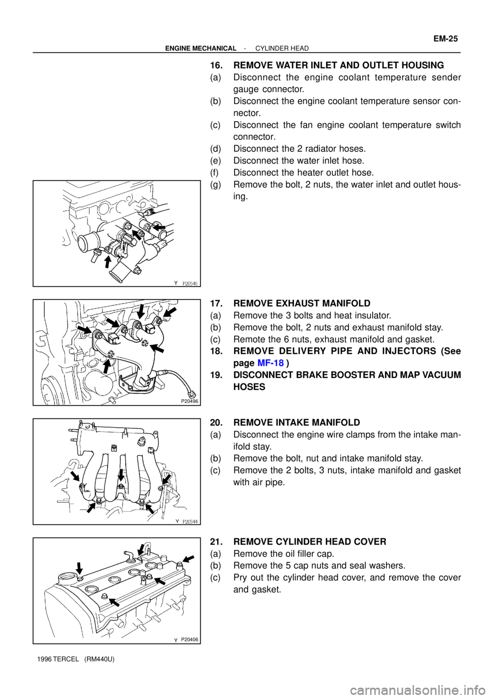
16. REMOVE WATER INLET AND OUTLET HOUSING
(a) Disconnect the engine coolant temperature sender
gauge connector.
(b) Disconnect the engine coolant temperature sensor con-
nector.
(c) Disconnect the fan engine coolant temperature switch
connector.
(d) Disconnect the 2 radiator hoses.
(e) Disconnect the water inlet hose.
(f) Disconnect the heater outlet hose.
(g) Remove the bolt, 2 nuts, the water inlet and outlet hous-
ing.
17. REMOVE EXHAUST MANIFOLD
(a) Remove the 3 bolts and heat insulator.
(b) Remove the bolt, 2 nuts and exhaust manifold stay.
(c) Remote the 6 nuts, exhaust manifold and gasket.
18. REMOVE DELIVERY PIPE AND INJECTORS (See
page MF-18)
19. DISCONNECT BRAKE BOOSTER AND MAP VACUUM
HOSES
20. REMOVE INTAKE MANIFOLD
(a) Disconnect the engine wire clamps from the intake man-
ifold stay.
(b) Remove the bolt, nut and intake manifold stay.
(c) Remove the 2 bolts, 3 nuts, intake manifold and gasket
with air pipe.
21. REMOVE CYLINDER HEAD COVER
(a) Remove the oil filler cap.
(b) Remove the 5 cap nuts and seal washers.
(c) Pry out the cylinder head cover, and remove the cover
and gasket.
Page 448 of 1202
P20361
P20532
Shop
Rag
Tape
P20363
P20357
P20364
EM-26
- ENGINE MECHANICALCYLINDER HEAD
1996 TERCEL (RM440U)
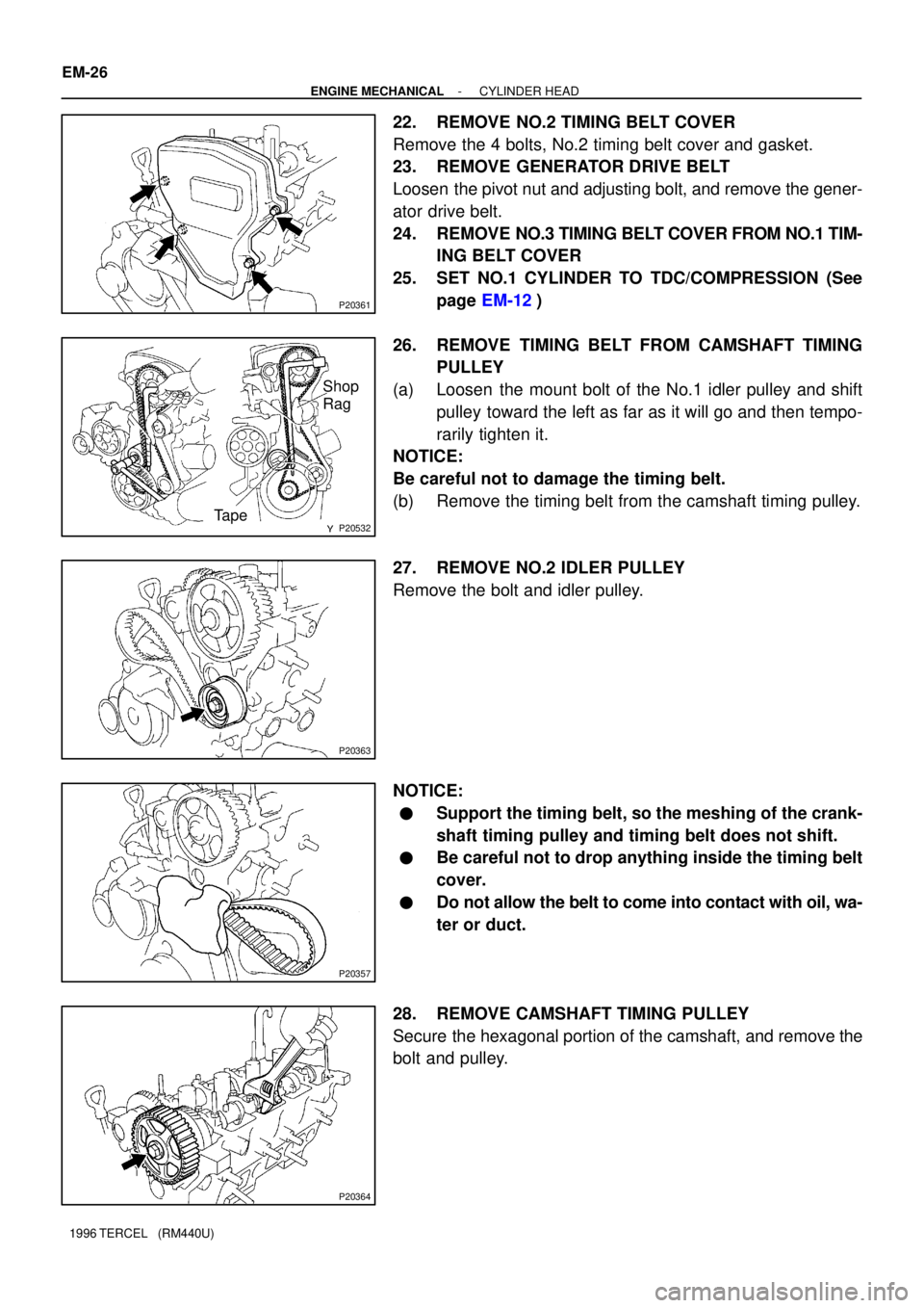
22. REMOVE NO.2 TIMING BELT COVER
Remove the 4 bolts, No.2 timing belt cover and gasket.
23. REMOVE GENERATOR DRIVE BELT
Loosen the pivot nut and adjusting bolt, and remove the gener-
ator drive belt.
24. REMOVE NO.3 TIMING BELT COVER FROM NO.1 TIM-
ING BELT COVER
25. SET NO.1 CYLINDER TO TDC/COMPRESSION (See
page EM-12)
26. REMOVE TIMING BELT FROM CAMSHAFT TIMING
PULLEY
(a) Loosen the mount bolt of the No.1 idler pulley and shift
pulley toward the left as far as it will go and then tempo-
rarily tighten it.
NOTICE:
Be careful not to damage the timing belt.
(b) Remove the timing belt from the camshaft timing pulley.
27. REMOVE NO.2 IDLER PULLEY
Remove the bolt and idler pulley.
NOTICE:
�Support the timing belt, so the meshing of the crank-
shaft timing pulley and timing belt does not shift.
�Be careful not to drop anything inside the timing belt
cover.
�Do not allow the belt to come into contact with oil, wa-
ter or duct.
28. REMOVE CAMSHAFT TIMING PULLEY
Secure the hexagonal portion of the camshaft, and remove the
bolt and pulley.
Page 449 of 1202
P20412
Service Bolt Hole
P20409
P20415
Main Gear
Sub-Gear Service
Bolt
- ENGINE MECHANICALCYLINDER HEAD
EM-27
1996 TERCEL (RM440U)
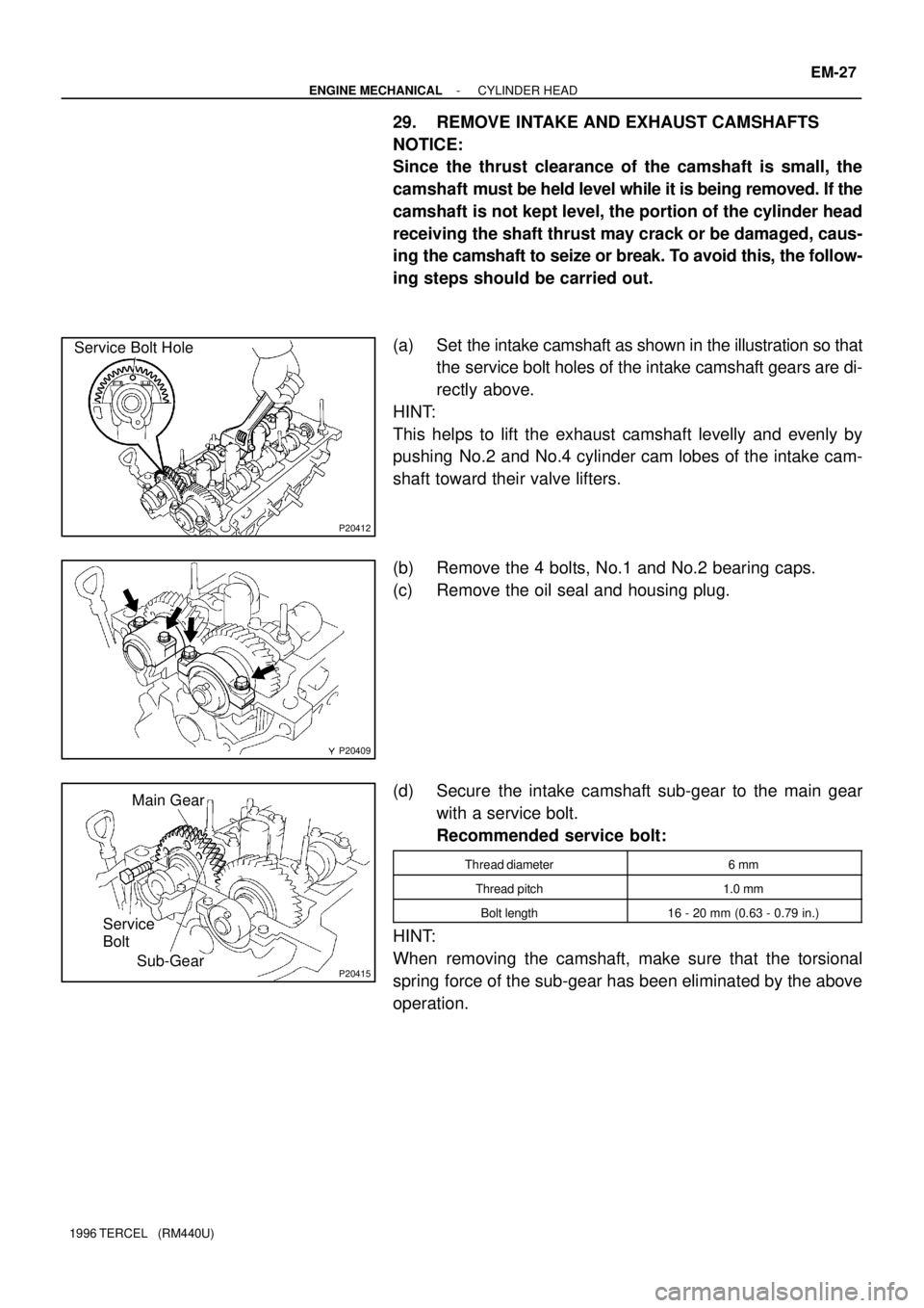
29. REMOVE INTAKE AND EXHAUST CAMSHAFTS
NOTICE:
Since the thrust clearance of the camshaft is small, the
camshaft must be held level while it is being removed. If the
camshaft is not kept level, the portion of the cylinder head
receiving the shaft thrust may crack or be damaged, caus-
ing the camshaft to seize or break. To avoid this, the follow-
ing steps should be carried out.
(a) Set the intake camshaft as shown in the illustration so that
the service bolt holes of the intake camshaft gears are di-
rectly above.
HINT:
This helps to lift the exhaust camshaft levelly and evenly by
pushing No.2 and No.4 cylinder cam lobes of the intake cam-
shaft toward their valve lifters.
(b) Remove the 4 bolts, No.1 and No.2 bearing caps.
(c) Remove the oil seal and housing plug.
(d) Secure the intake camshaft sub-gear to the main gear
with a service bolt.
Recommended service bolt:
Thread diameter6 mm
Thread pitch1.0 mm
Bolt length16 - 20 mm (0.63 - 0.79 in.)
HINT:
When removing the camshaft, make sure that the torsional
spring force of the sub-gear has been eliminated by the above
operation.
Page 450 of 1202
Z14275
7
351
48
22
6
P20359
Z14276
P20358
P20417
SST EM-28
- ENGINE MECHANICALCYLINDER HEAD
1996 TERCEL (RM440U)
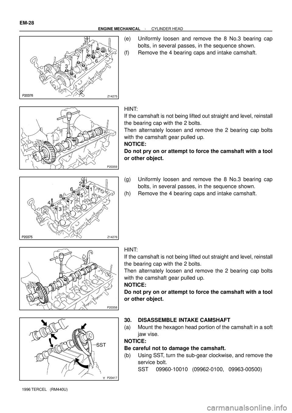
(e) Uniformly loosen and remove the 8 No.3 bearing cap
bolts, in several passes, in the sequence shown.
(f) Remove the 4 bearing caps and intake camshaft.
HINT:
If the camshaft is not being lifted out straight and level, reinstall
the bearing cap with the 2 bolts.
Then alternately loosen and remove the 2 bearing cap bolts
with the camshaft gear pulled up.
NOTICE:
Do not pry on or attempt to force the camshaft with a tool
or other object.
(g) Uniformly loosen and remove the 8 No.3 bearing cap
bolts, in several passes, in the sequence shown.
(h) Remove the 4 bearing caps and intake camshaft.
HINT:
If the camshaft is not being lifted out straight and level, reinstall
the bearing cap with the 2 bolts.
Then alternately loosen and remove the 2 bearing cap bolts
with the camshaft gear pulled up.
NOTICE:
Do not pry on or attempt to force the camshaft with a tool
or other object.
30. DISASSEMBLE INTAKE CAMSHAFT
(a) Mount the hexagon head portion of the camshaft in a soft
jaw vise.
NOTICE:
Be careful not to damage the camshaft.
(b) Using SST, turn the sub-gear clockwise, and remove the
service bolt.
SST 09960-10010 (09962-0100, 09963-00500)
Page 451 of 1202
Z14274
(g)(c)
(e)(d)
P20420
Bi-Hexagon Wrench
12
3
4 56 7
8 9
10
P20405
- ENGINE MECHANICALCYLINDER HEAD
EM-29
1996 TERCEL (RM440U)
(c) Using snap ring pliers, remove the snap ring.
(d) Remove the wave washer.
(e) Remove the camshaft sub-gear.
(f) Remove the camshaft gear spring.
31. REMOVE CYLINDER HEAD
(a) Using a bi-hexagon wrench 8 mm, uniformly loosen and
remove the 10 cylinder head bolts, in several passes, in
the sequence shown.
NOTICE:
Cylinder head warpage or cracking could result from re-
moving bolts in incorrect order.
(b) Lift the cylinder head from the dowels on the cylinder
block and place the head on wooden blocks on a bench.
HINT:
If the cylinder head is difficult to lift off, pry with a screwdriver be-
tween the cylinder head and block saliences.
NOTICE:
Be careful not to damage the contact surfaces of the cylin-
der head and cylinder block.
Page 452 of 1202
EM9937
EM0JZ-03
P20416
SST
EM9939
EM-30
- ENGINE MECHANICALCYLINDER HEAD
1996 TERCEL (RM440U)
DISASSEMBLY
1. REMOVE NO.2 ENGINE HANGER
2. REMOVE STUD BOLT FOR CYLINDER HEAD COVER
3. REMOVE VALVE LIFTERS AND SHIMS
HINT:
Arrange the valve lifters and shims in correct order.
4. REMOVE VALVES
(a) Using SST, compress the valve spring and remove the 2
keepers.
SST 09202-70010
(b) Remove the spring retainer, valve spring, valve and
spring seat.
HINT:
Arrange the valves, valve springs, spring seats and spring re-
tainers in correct order.
(c) Using needle-nose pliers, remove the oil seal.
Page 453 of 1202
EM0K0-05
P20381
P20380
P20350
P20353
EG0031
- ENGINE MECHANICALCYLINDER HEAD
EM-31
1996 TERCEL (RM440U)
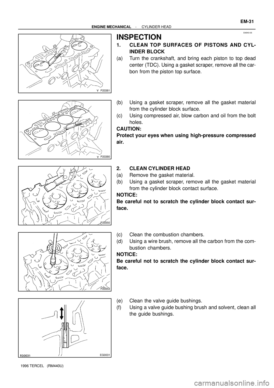
INSPECTION
1. CLEAN TOP SURFACES OF PISTONS AND CYL-
INDER BLOCK
(a) Turn the crankshaft, and bring each piston to top dead
center (TDC). Using a gasket scraper, remove all the car-
bon from the piston top surface.
(b) Using a gasket scraper, remove all the gasket material
from the cylinder block surface.
(c) Using compressed air, blow carbon and oil from the bolt
holes.
CAUTION:
Protect your eyes when using high-pressure compressed
air.
2. CLEAN CYLINDER HEAD
(a) Remove the gasket material.
(b) Using a gasket scraper, remove all the gasket material
from the cylinder block contact surface.
NOTICE:
Be careful not to scratch the cylinder block contact sur-
face.
(c) Clean the combustion chambers.
(d) Using a wire brush, remove all the carbon from the com-
bustion chambers.
NOTICE:
Be careful not to scratch the cylinder block contact sur-
face.
(e) Clean the valve guide bushings.
(f) Using a valve guide bushing brush and solvent, clean all
the guide bushings.
Page 465 of 1202
Z14254
Painted
Black Painted Silver Intake Exhaust
P20416
SST
EM9933
- ENGINE MECHANICALCYLINDER HEAD
EM-43
1996 TERCEL (RM440U)
HINT:
The intake valve oil seal is silver and the exhaust valve oil seal
is black.
(b) Install the valve.
(c) Install the spring seat.
(d) Install the valve spring.
(e) Install the spring retainer.
(f) Using SST, compress the valve spring and place the 2
keepers around the valve stem.
SST 09202-70010
(g) Using a plastic-faced hammer, lightly tap the valve stem
tip to assure proper fit.
3. INSTALL VALVE LIFTERS AND SHIMS
(a) Install the valve lifter and shim.
(b) Check that the valve lifter rotates smoothly by hand.
4. INSTALL STUD BOLT FOR CYLINDER HEAD COVER
5. INSTALL NO.2 ENGINE HANGER
Torque:
No. 1
21 N´m (210 kgf´cm, 15 ft´lbf)
No. 2
53 N´m (530 kgf´cm, 38 ft´lbf)