Page 474 of 1202

EM-52
- ENGINE MECHANICALCYLINDER HEAD
1996 TERCEL (RM440U)
HINT:
Avoid applying an excess amount to the surface. Be especially
careful near oil passages.
�Parts must be assembled within 15 minutes of ap-
plication. Otherwise, the material must be removed
and reapplied.
�Immediately remove nozzle from tube and reinstall
cap.
�Do not pour in any coolant until at least 2 hours after
installation is completed.
(c) Install the water outlet housing with the bolt and 2 nuts.
Torque: 17.5 N´m (175 kgf´cm, 13 ft´lbf)
(d) Connect the 2 radiator hoses.
(e) Connect the water inlet hose.
(f) Connect the heater outlet hose.
(g) Connect the engine coolant temperature sensor connec-
tor.
(h) Connect the engine coolant temperature sender gauge
connector.
(i) Connect the fan engine coolant temperature switch con-
nector.
20. INSTALL CAMSHAFT POSITION SENSOR AND EGR
VSV
(a) Install a new O-ring to the position sensor.
(b) Install the position sensor with the bolt.
Torque: 8.0 N´m (80 kgf´cm, 69 in.´lbf)
(c) Install the EGR VSV with the bolt.
Torque: 17.5 N´m (175 kgf´cm, 13 in.´lbf)
(d) Connect the position sensor and EGR VSV connectors.
21. INSTALL EGR VALVE AND VACUUM MODULATOR
(a) Install a new gasket and the EGR valve with the 2 nuts.
Torque: 30 N´m (300 kgf´cm, 22 in.´lbf)
(b) Install the EGR vacuum modulator and bracket with the
bolt.
Page 475 of 1202

EG0023
P20290
- ENGINE MECHANICALCYLINDER HEAD
EM-53
1996 TERCEL (RM440U)
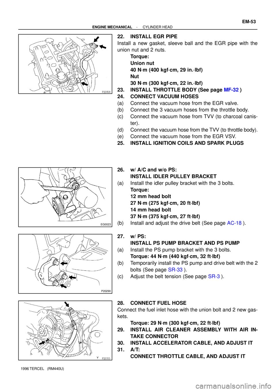
22. INSTALL EGR PIPE
Install a new gasket, sleeve ball and the EGR pipe with the
union nut and 2 nuts.
Torque:
Union nut
40 N´m (400 kgf´cm, 29 in.´lbf)
Nut
30 N´m (300 kgf´cm, 22 in.´lbf)
23. INSTALL THROTTLE BODY (See page MF-32)
24. CONNECT VACUUM HOSES
(a) Connect the vacuum hose from the EGR valve.
(b) Connect the 3 vacuum hoses from the throttle body.
(c) Connect the vacuum hose from TVV (to charcoal canis-
ter).
(d) Connect the vacuum hose from the TVV (to throttle body).
(e) Connect the vacuum hose from the EGR VSV.
25. INSTALL IGNITION COILS AND SPARK PLUGS
26. w/ A/C and w/o PS:
INSTALL IDLER PULLEY BRACKET
(a) Install the idler pulley bracket with the 3 bolts.
Torque:
12 mm head bolt
27 N´m (275 kgf´cm, 20 ft´lbf)
14 mm head bolt
37 N´m (375 kgf´cm, 27 ft´lbf)
(b) Install and adjust the drive belt (See page AC-18).
27. w/ PS:
INSTALL PS PUMP BRACKET AND PS PUMP
(a) Install the PS pump bracket with the 3 bolts.
Torque: 44 N´m (440 kgf´cm, 32 ft´lbf)
(b) Temporarily install the PS pump and drive belt with the 2
bolts (See page SR-33).
(c) Adjust the belt tension (See page SR-3).
28. CONNECT FUEL HOSE
Connect the fuel inlet hose with the union bolt and 2 new gas-
kets.
Torque: 29 N´m (300 kgf´cm, 22 ft´lbf)
29. INSTALL AIR CLEANER ASSEMBLY WITH AIR IN-
TAKE CONNECTOR
30. INSTALL ACCELERATOR CABLE, AND ADJUST IT
31. A/T:
CONNECT THROTTLE CABLE, AND ADJUST IT
Page 476 of 1202
P20160
EM-54
- ENGINE MECHANICALCYLINDER HEAD
1996 TERCEL (RM440U)
32. CONNECT FRONT EXHAUST PIPE
(a) Place a new gasket on the exhaust pipe.
(b) Connect the exhaust pipe to the exhaust manifold with
the 2 compression spring and 2 bolts.
Torque: 62 N´m (630 kgf´cm, 46 ft´lbf)
33. INSTALL RH ENGINE UNDER COVER
34. FILL WITH ENGINE COOLANT (See page CO-2)
35. START ENGINE AND CHECK FOR LEAKS
36. PERFORM ENGINE ADJUSTMENT
37. PERFORM ROAD TEST
Check for abnormal noise, shock, slippage, correct shift points
and smooth operation.
38. RECHECK ENGINE COOLANT AND ENGINE OIL LEV-
ELS
Page 485 of 1202
P20246
P00352
P20285
M/T
P20866
A132L A/T
A242L A/T
- ENGINE MECHANICALENGINE UNIT
EM-63
1996 TERCEL (RM440U)
(d) Keep the engine level, and align RH and LH engine
mountings with the body bracket.
(e) Attach the RH engine mounting insulator to the mounting
bracket and body, and temporarily install the through bolt,
2 bolts and nut.
(f) Install the LH engine mounting bracket to the transaxle
and mounting insulator with the 5 bolts. Torque the bolts.
Torque:
Bracket to transaxle (bolt head: NT)
65 N´m (650 kgf´cm, 47 ft´lbf)
Bracket to insulator (bolt head: 7T)
49 N´m (490 kgf´cm, 35 ft´lbf)
(g) Connect the ground strap with the bolt.
Torque: 49 N´m (490 kgf´cm, 35 ft´lbf)
Page 509 of 1202

P20551
P20530
Front
Z14291
1
2 3
45
6
7
89
10
EM3480
P20569
Front Mark
(Cavity)
FrontPush
- ENGINE MECHANICALCYLINDER BLOCK
EM-87
1996 TERCEL (RM440U)
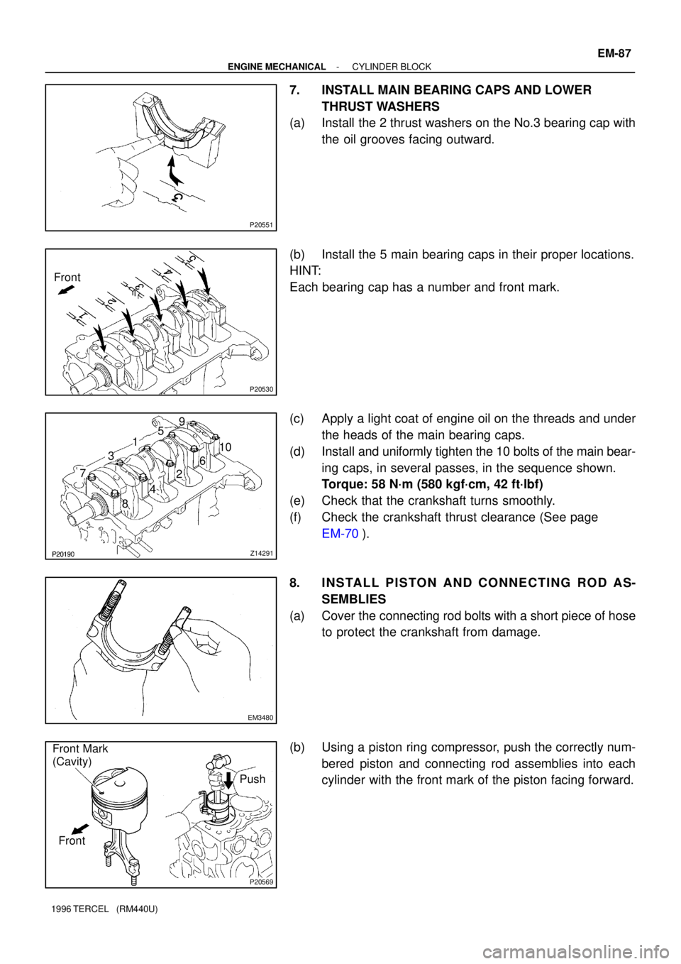
7. INSTALL MAIN BEARING CAPS AND LOWER
THRUST WASHERS
(a) Install the 2 thrust washers on the No.3 bearing cap with
the oil grooves facing outward.
(b) Install the 5 main bearing caps in their proper locations.
HINT:
Each bearing cap has a number and front mark.
(c) Apply a light coat of engine oil on the threads and under
the heads of the main bearing caps.
(d) Install and uniformly tighten the 10 bolts of the main bear-
ing caps, in several passes, in the sequence shown.
Torque: 58 N´m (580 kgf´cm, 42 ft´lbf)
(e) Check that the crankshaft turns smoothly.
(f) Check the crankshaft thrust clearance (See page
EM-70).
8. INSTALL PISTON AND CONNECTING ROD AS-
SEMBLIES
(a) Cover the connecting rod bolts with a short piece of hose
to protect the crankshaft from damage.
(b) Using a piston ring compressor, push the correctly num-
bered piston and connecting rod assemblies into each
cylinder with the front mark of the piston facing forward.
Page 512 of 1202
P20750
P20480
SST
P20545
EM9412
EM7333
EM-90
- ENGINE MECHANICALCYLINDER BLOCK
1996 TERCEL (RM440U)
15. INSTALL RH ENGINE MOUNTING BRACKET
Torque: 58 N´m (590 kgf´cm, 43 ft´lbf)
16. INSTALL KNOCK SENSOR
Using SST, install the knock sensor.
SST 09816-30010
Torque: 45 N´m (450 kgf´cm, 33 ft´lbf)
17. INSTALL GENERATOR BRACKET
Torque: 24 N´m (240 kgf´cm, 18 ft´lbf)
18. INSTALL WATER PUMP WITH WATER INLET PIPE
19. INSTALL OIL DIPSTICK GUIDE AND GENERATOR AD-
JUSTING BAR
20. INSTALL CYLINDER HEAD
21. INSTALL TIMING BELT AND PULLEYS
22. REMOVE ENGINE STAND
23. INSTALL REAR END PLATE
Torque: 10 N´m (100 kgf´cm, 7 ft´lbf)
24. M/T:
INSTALL FLYWHEEL
(a) Apply adhesive to 2 or 3 threads of new mounting bolt
end.
Adhesive:
Part No. 08833-00070, THREE BOND 1324 or
equivalent
Page 528 of 1202

P20175
New
Gasket
FI1654
Fulcrum Length
SST
30 cm
FI4295
CORRECT
WRONG
WRONG Delivery Pipe O-Ring
Grommet
Injector
FI4296
Delivery
Pipe
O-Ring
Grommet
InjectorCylinder Head
- MFIMFI SYSTEM
MF-3
527 Author�: Date�:
1996 TERCEL (RM440U)
(b) When connecting the union bolt on the high pressure pipe
union, observe these procedures:
(1) Always use 2 new gaskets.
(2) Tighten the union bolt by hand.
(3) Tighten the union bolt to the specified torque.
Torque: 29.0 N´m (290 kgf´cm, 22 ft´lbf)
(c) When connecting the flare nut on the high pressure pipe
union, observe these procedures:
(1) Apply a light coat of engine oil to the flare nut, and
tighten the flare nut by hand.
(2) Using SST, tighten the flare nut to specified torque.
SST 09631-22020
NOTICE:
Do not rotate the fuel pipe, when tightening the flare nut.
Torque: 30 N´m (300 kgf´cm, 23 ft´lbf)
HINT:
Use a torque wrench with a fulcrum length of 30 cm (11.81 in.).
(d) Observe these precautions when removing and installing
the injectors.
(1) Never reuse the O-ring.
(2) When placing a new O-ring on the injector, take
care not to damage it in any way.
(3) Coat a new O-ring with spindle oil or gasoline be-
fore installing-never use engine, gear or brake oil.
(e) Install the injector in the delivery pipe and cylinder head
as shown in the illustration.
Page 543 of 1202
SF0X2-03
MF-18
- MFIINJECTOR
1996 TERCEL (RM440U)
REMOVAL
1. DISCONNECT VACUUM SEMSING HOSE FROM FUEL
PRESSURE REGULATOR
2. DISCONNECT FUEL RETURN HOSE FROM FUEL RE-
TURN PIPE
NOTICE:
Catch leaking in a container.
3. DISCONNECT FUEL INLET HOSE FROM DELIVERY
PIPE
(a) Disconnect the engine wire clamp from the No. 2 engine
hanger.
(b) Remove the union bolt, 2 gaskets and inlet hose.
4. DISCONNECT ENGINE WIRE
(a) Disconnect the engine wire from the surge tank stay.
(b) Disconnect the 4 injector connectors.
5. REMOVE DELIVERY PIPE WITH INJECTORS
(a) Remove the 2 bolts and delivery pipe together with the 4
injectors.
NOTICE:
Be careful not to drop the injectors when removing the de-
livery pipe.
(b) Pull out the 4 injectors from the delivery pipe.
(c) Remove the 2 spacers and 4 insulators from the cylinder
head.
(d) Remove the O-ring and grommet from each injector.