Page 497 of 1202
P20488
EM9443
Plastigage
Z14291
4
810
6
2 159
73
EM9442
- ENGINE MECHANICALCYLINDER BLOCK
EM-75
1996 TERCEL (RM440U)
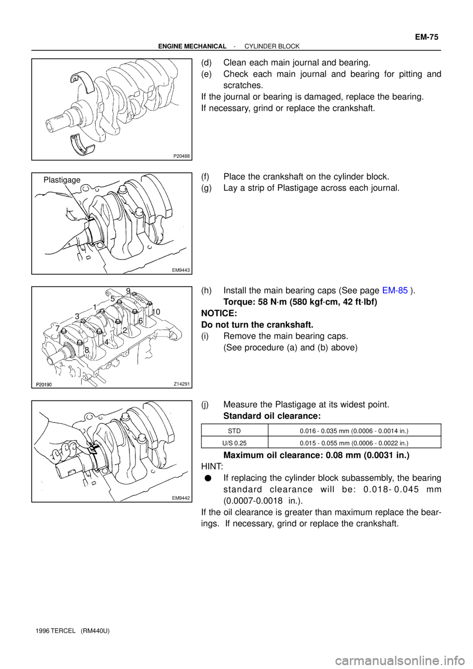
(d) Clean each main journal and bearing.
(e) Check each main journal and bearing for pitting and
scratches.
If the journal or bearing is damaged, replace the bearing.
If necessary, grind or replace the crankshaft.
(f) Place the crankshaft on the cylinder block.
(g) Lay a strip of Plastigage across each journal.
(h) Install the main bearing caps (See page EM-85).
Torque: 58 N´m (580 kgf´cm, 42 ft´lbf)
NOTICE:
Do not turn the crankshaft.
(i) Remove the main bearing caps.
(See procedure (a) and (b) above)
(j) Measure the Plastigage at its widest point.
Standard oil clearance:
STD0.016 - 0.035 mm (0.0006 - 0.0014 in.)
U/S 0.250.015 - 0.055 mm (0.0006 - 0.0022 in.)
Maximum oil clearance: 0.08 mm (0.0031 in.)
HINT:
�If replacing the cylinder block subassembly, the bearing
standard clearance will be: 0.018- 0.045 mm
(0.0007-0.0018 in.).
If the oil clearance is greater than maximum replace the bear-
ings. If necessary, grind or replace the crankshaft.
Page 509 of 1202
P20551
P20530
Front
Z14291
1
2 3
45
6
7
89
10
EM3480
P20569
Front Mark
(Cavity)
FrontPush
- ENGINE MECHANICALCYLINDER BLOCK
EM-87
1996 TERCEL (RM440U)
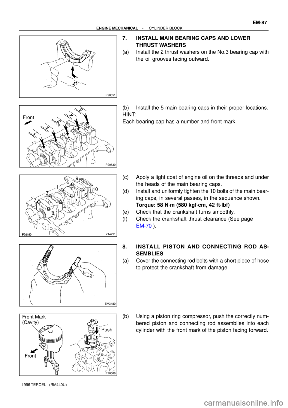
7. INSTALL MAIN BEARING CAPS AND LOWER
THRUST WASHERS
(a) Install the 2 thrust washers on the No.3 bearing cap with
the oil grooves facing outward.
(b) Install the 5 main bearing caps in their proper locations.
HINT:
Each bearing cap has a number and front mark.
(c) Apply a light coat of engine oil on the threads and under
the heads of the main bearing caps.
(d) Install and uniformly tighten the 10 bolts of the main bear-
ing caps, in several passes, in the sequence shown.
Torque: 58 N´m (580 kgf´cm, 42 ft´lbf)
(e) Check that the crankshaft turns smoothly.
(f) Check the crankshaft thrust clearance (See page
EM-70).
8. INSTALL PISTON AND CONNECTING ROD AS-
SEMBLIES
(a) Cover the connecting rod bolts with a short piece of hose
to protect the crankshaft from damage.
(b) Using a piston ring compressor, push the correctly num-
bered piston and connecting rod assemblies into each
cylinder with the front mark of the piston facing forward.
Page 510 of 1202
EM3481
Front Mark
(Protrusion)
Front
EM3448
P20475
Seal Packing
A'B'
A
B
A - A' B - B' EM-88
- ENGINE MECHANICALCYLINDER BLOCK
1996 TERCEL (RM440U)
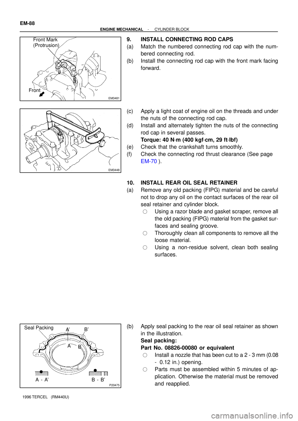
9. INSTALL CONNECTING ROD CAPS
(a) Match the numbered connecting rod cap with the num-
bered connecting rod.
(b) Install the connecting rod cap with the front mark facing
forward.
(c) Apply a light coat of engine oil on the threads and under
the nuts of the connecting rod cap.
(d) Install and alternately tighten the nuts of the connecting
rod cap in several passes.
Torque: 40 N´m (400 kgf´cm, 29 ft´lbf)
(e) Check that the crankshaft turns smoothly.
(f) Check the connecting rod thrust clearance (See page
EM-70).
10. INSTALL REAR OIL SEAL RETAINER
(a) Remove any old packing (FIPG) material and be careful
not to drop any oil on the contact surfaces of the rear oil
seal retainer and cylinder block.
�Using a razor blade and gasket scraper, remove all
the old packing (FIPG) material from the gasket sur-
faces and sealing groove.
�Thoroughly clean all components to remove all the
loose material.
�Using a non-residue solvent, clean both sealing
surfaces.
(b) Apply seal packing to the rear oil seal retainer as shown
in the illustration.
Seal packing:
Part No. 08826-00080 or equivalent
�Install a nozzle that has been cut to a 2 - 3 mm (0.08
- 0.12 in.) opening.
�Parts must be assembled within 5 minutes of ap-
plication. Otherwise the material must be removed
and reapplied.
Page 511 of 1202
EM9966
P20476
12 mm
Hexagon
Wrench
P00496
Adhesive
P20479
SST
- ENGINE MECHANICALCYLINDER BLOCK
EM-89
1996 TERCEL (RM440U)
�Immediately remove nozzle from the tube and rein-
stall cap.
(c) Install the oil seal retainer with the 4 bolts.
Torque: 7.5 N´m (75 kgf´cm, 65 in.´lbf)
11. INSTALL OIL FILTER UNION
Using a 12 mm hexagon wrench, install the oil filter union.
Torque: 25 N´m (250 kgf´cm, 18 ft´lbf)
12. INSTALL OIL PUMP AND PRESSURE REGULATOR
VA LV E
13. INSTALL OIL PRESSURE SWITCH
(a) Clean the switch threads and cylinder block switch holes
of any sealer, oil or foreign materials. Remove any oil with
kerosene or gasoline.
(b) Apply adhesive to 2 or 3 threads of the switch end.
Adhesive:
Part No. 08833-00080, THREE BOND 1344,
LOCTITE 242 or equivalent
(c) Using SST, install the oil pressure switch.
SST 09816-30010
Torque: 13 N´m (130 kgf´cm, 9 ft´lbf)
14. INSTALL OIL FILTER (See page LU-1)
Page 512 of 1202
P20750
P20480
SST
P20545
EM9412
EM7333
EM-90
- ENGINE MECHANICALCYLINDER BLOCK
1996 TERCEL (RM440U)
15. INSTALL RH ENGINE MOUNTING BRACKET
Torque: 58 N´m (590 kgf´cm, 43 ft´lbf)
16. INSTALL KNOCK SENSOR
Using SST, install the knock sensor.
SST 09816-30010
Torque: 45 N´m (450 kgf´cm, 33 ft´lbf)
17. INSTALL GENERATOR BRACKET
Torque: 24 N´m (240 kgf´cm, 18 ft´lbf)
18. INSTALL WATER PUMP WITH WATER INLET PIPE
19. INSTALL OIL DIPSTICK GUIDE AND GENERATOR AD-
JUSTING BAR
20. INSTALL CYLINDER HEAD
21. INSTALL TIMING BELT AND PULLEYS
22. REMOVE ENGINE STAND
23. INSTALL REAR END PLATE
Torque: 10 N´m (100 kgf´cm, 7 ft´lbf)
24. M/T:
INSTALL FLYWHEEL
(a) Apply adhesive to 2 or 3 threads of new mounting bolt
end.
Adhesive:
Part No. 08833-00070, THREE BOND 1324 or
equivalent
Page 513 of 1202
EM9410
1
2 3
45
6
- ENGINE MECHANICALCYLINDER BLOCK
EM-91
1996 TERCEL (RM440U)
(b) Install the flywheel on the crankshaft.
(c) Install and uniformly tighten the mounting bolts, in several
passes, in the sequence shown.
Torque: 90 N´m (900 kgf´cm, 65 ft´lbf)
25. A/T:
INSTALL DRIVE PLATE (See step 24)
26. M/T:
INSTALL CLUTCH DISC AND COVER
Page 520 of 1202
Port B
Port C
(a)
(b)
P05838
EC-6
- EMISSION CONTROLEVAPORATIVE EMISSION (EVAP) CONTROL SYSTEM
519 Author�: Date�:
1996 TERCEL (RM440U)
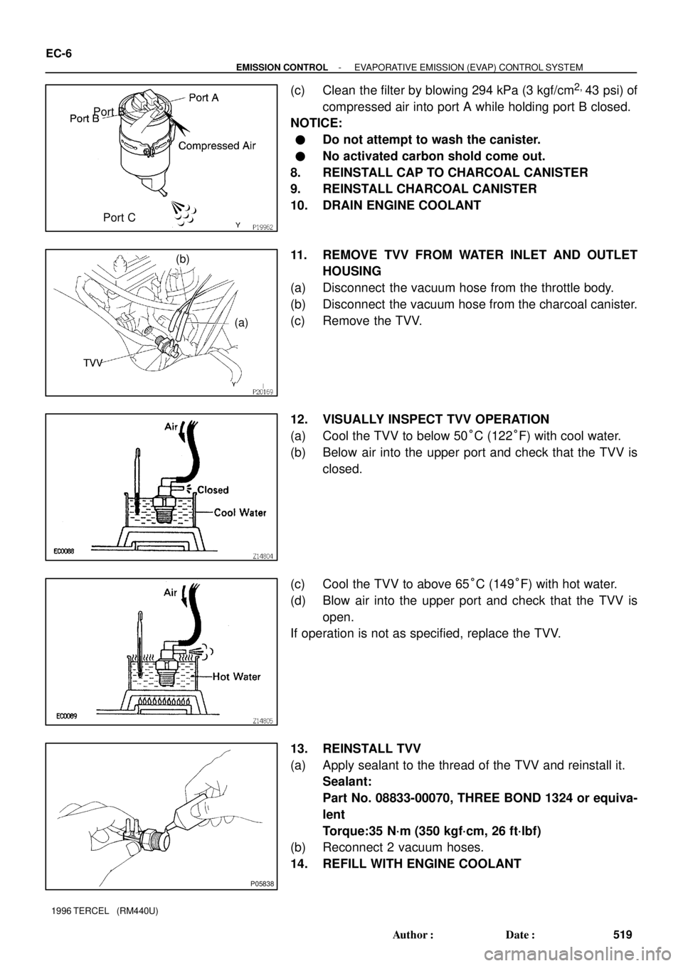
(c) Clean the filter by blowing 294 kPa (3 kgf/cm2,
43 psi) of
compressed air into port A while holding port B closed.
NOTICE:
�Do not attempt to wash the canister.
�No activated carbon shold come out.
8. REINSTALL CAP TO CHARCOAL CANISTER
9. REINSTALL CHARCOAL CANISTER
10. DRAIN ENGINE COOLANT
11. REMOVE TVV FROM WATER INLET AND OUTLET
HOUSING
(a) Disconnect the vacuum hose from the throttle body.
(b) Disconnect the vacuum hose from the charcoal canister.
(c) Remove the TVV.
12. VISUALLY INSPECT TVV OPERATION
(a) Cool the TVV to below 50°C (122°F) with cool water.
(b) Below air into the upper port and check that the TVV is
closed.
(c) Cool the TVV to above 65°C (149°F) with hot water.
(d) Blow air into the upper port and check that the TVV is
open.
If operation is not as specified, replace the TVV.
13. REINSTALL TVV
(a) Apply sealant to the thread of the TVV and reinstall it.
Sealant:
Part No. 08833-00070, THREE BOND 1324 or equiva-
lent
Torque:35 N´m (350 kgf´cm, 26 ft´lbf)
(b) Reconnect 2 vacuum hoses.
14. REFILL WITH ENGINE COOLANT
Page 523 of 1202
(a)
(b)
- EMISSION CONTROLEXHAUST GAS RECIRCULATION (EGR) SYSTEM
EC-9
1996 TERCEL (RM440U)
7. INSPECT EGR VALVE
(a) Disconnect the vacuum hose from the EGR valve.
(b) Apply vacuum directly to the EGR valve with the engine
idling.
(c) Check that the engine runs rough or dies.
(d) Reconnect the vacuum hoses to the proper locations.
HINT:
As exhaust gas is increasingly recirculated, the engine will start
to misfire.
8. VSV ISPECTION (See page MF-42)
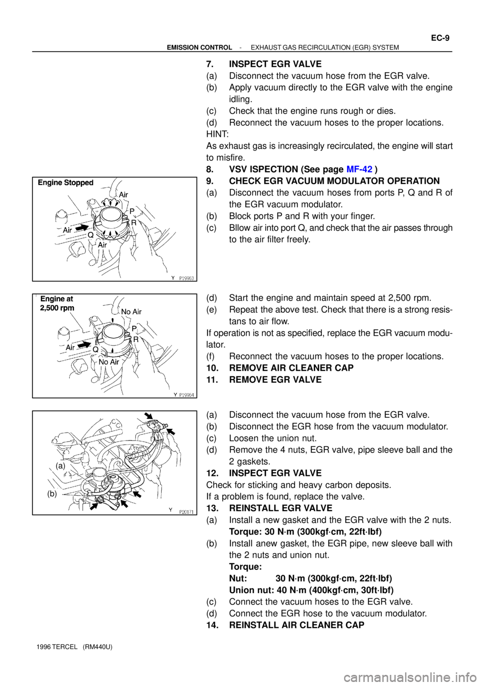
9. CHECK EGR VACUUM MODULATOR OPERATION
(a) Disconnect the vacuum hoses from ports P, Q and R of
the EGR vacuum modulator.
(b) Block ports P and R with your finger.
(c) Bllow air into port Q, and check that the air passes through
to the air filter freely.
(d) Start the engine and maintain speed at 2,500 rpm.
(e) Repeat the above test. Check that there is a strong resis-
tans to air flow.
If operation is not as specified, replace the EGR vacuum modu-
lator.
(f) Reconnect the vacuum hoses to the proper locations.
10. REMOVE AIR CLEANER CAP
11. REMOVE EGR VALVE
(a) Disconnect the vacuum hose from the EGR valve.
(b) Disconnect the EGR hose from the vacuum modulator.
(c) Loosen the union nut.
(d) Remove the 4 nuts, EGR valve, pipe sleeve ball and the
2 gaskets.
12. INSPECT EGR VALVE
Check for sticking and heavy carbon deposits.
If a problem is found, replace the valve.
13. REINSTALL EGR VALVE
(a) Install a new gasket and the EGR valve with the 2 nuts.
Torque: 30 N´m (300kgf´cm, 22ft´lbf)
(b) Install anew gasket, the EGR pipe, new sleeve ball with
the 2 nuts and union nut.
Torque:
Nut: 30 N´m (300kgf´cm, 22ft´lbf)
Union nut: 40 N´m (400kgf´cm, 30ft´lbf)
(c) Connect the vacuum hoses to the EGR valve.
(d) Connect the EGR hose to the vacuum modulator.
14. REINSTALL AIR CLEANER CAP