Page 316 of 1202
R12884
SRS ECU
A1212 V
EA14
Tc
E
1
J/C
A A
DLC111
EC
BR
Tc
325
P-B P-B P-BABS ECU
J1
BR
R13006
TcE1
DLC1
- DIAGNOSTICSANTI-LOCK BRAKE SYSTEM
DI-141
1996 TERCEL (RM440U)
Tc Terminal Circuit
CIRCUIT DESCRIPTION
Connecting between terminals Tc and E1 of the DLC1 cause the ECU to display the DTC by flashing the ABS
warning light.
WIRING DIAGRAM
INSPECTION PROCEDURE
1 Check voltage between terminals Tc and E1 of DLC1.
CHECK:
(a) Turn the ignition switch ON.
(b) Measure the voltage between terminals Tc and E
1 of the
DLC1.
OK:
Voltage: 10 - 14 V
OK If ABS warning light does not blink even after Tc
and E
1 are connected, ECU may be defective.
NG
DI4M0-02
Page 317 of 1202
DI-142
- DIAGNOSTICSANTI-LOCK BRAKE SYSTEM
1996 TERCEL (RM440U)
2 Check for open and short in harness and connector between ABS ECU and
DLC1, and DLC1 and body ground (See page IN-26).
NG Repair or replace harness or connector.
OK
Check and replace ABS ECU.
Page 318 of 1202
F00414
24ABS ECU
AA123DLC1
Ts
16
EC
E1TsL
B-RAEA13
B-RL12 V
J/C
J1
R13006
E1
DLC1
Tc
- DIAGNOSTICSANTI-LOCK BRAKE SYSTEM
DI-143
1996 TERCEL (RM440U)
Ts Terminal Circuit
CIRCUIT DESCRIPTION
The sensor check circuit detects abnormalities in the speed sensor signal which cannot be detected with
the DTC check.
Connecting terminals Ts and E
1 of the DLC1 in the engine compartment starts the check.
WIRING DIAGRAM
INSPECTION PROCEDURE
1 Check voltage between terminals Ts and E1 of DLC1.
CHECK:
(a) Turn the ignition switch ON.
(b) Measure the voltage between terminals Ts and E
1 of the
DLC1.
OK:
Voltage: 10 - 14 V
OK If ABS warning light does not blink even after Ts
and E
1 are connected, ECU may be defective.
NG
DI4M1-02
Page 319 of 1202
DI-144
- DIAGNOSTICSANTI-LOCK BRAKE SYSTEM
1996 TERCEL (RM440U)
2 Check for open and short in harness and connector between ABS ECU and
DLC1, and DLC1 and body ground (See page IN-26).
NG Repair or replace harness or connector.
OK
Check and replace ABS ECU.
Page 320 of 1202
R12175
- DIAGNOSTICSANTI-LOCK BRAKE SYSTEM
DI-145
1996 TERCEL (RM440U)
Check for Fluid Leakage
Check for fluid leakage from actuator or hydraulic lines.
DI4M2-01
Page 327 of 1202
DI4M8-01
N12263
Front Passenger
Airbag Assembly Steering Wheel Pad
(With Airbag)
Spiral Cable
Airbag Sensor Assembly
Instrument Panel
Junction BlockSRS Warning Light
DI-152
- DIAGNOSTICSSUPPLEMENTAL RESTRAINT SYSTEM
1996 TERCEL (RM440U)
PARTS LOCATION
Page 329 of 1202
DI4MA-01
DI-154
- DIAGNOSTICSSUPPLEMENTAL RESTRAINT SYSTEM
1996 TERCEL (RM440U)
PROBLEM SYMPTOMS TABLE
Proceed with troubleshooting of each circuit in the table below.
SymptomSuspect AreaSee page
�With the ignition switch at ACC or ON, the SRS warning light
sometimes lights up after approx. 6 seconds have elapsed.
�SRS warning light is always lit up even when ignition switch is in
the LOCK position.
�SRS warning light system malfunction
(Always lit up when ignition switch is in LOCK position.)DI-180
�With the ignition switch at ACC or ON, the SRS warning light
does not light up.�SRS warning light system malfunction
(Does not light up, when ignition switch is turned to ACC
or ON.)
DI-182
�DTC not displayed.
�SRS warning light is always lit up a DTC check procedure.
�DTC displayed without Tc and E1 terminal connection.
�Tc terminal circuitDI-185
Page 333 of 1202

AB0069
W01933
AB0118
R13006AB0069
AB0118
W02042
H00006
Airbag Sensor
Assembly
Spiral
Cable P Squib
D SquibP+
P-
D+ D-ACCON
or
Code 11
DLC1
Tc
E1
DI-158
- DIAGNOSTICSSUPPLEMENTAL RESTRAINT SYSTEM
1996 TERCEL (RM440U)
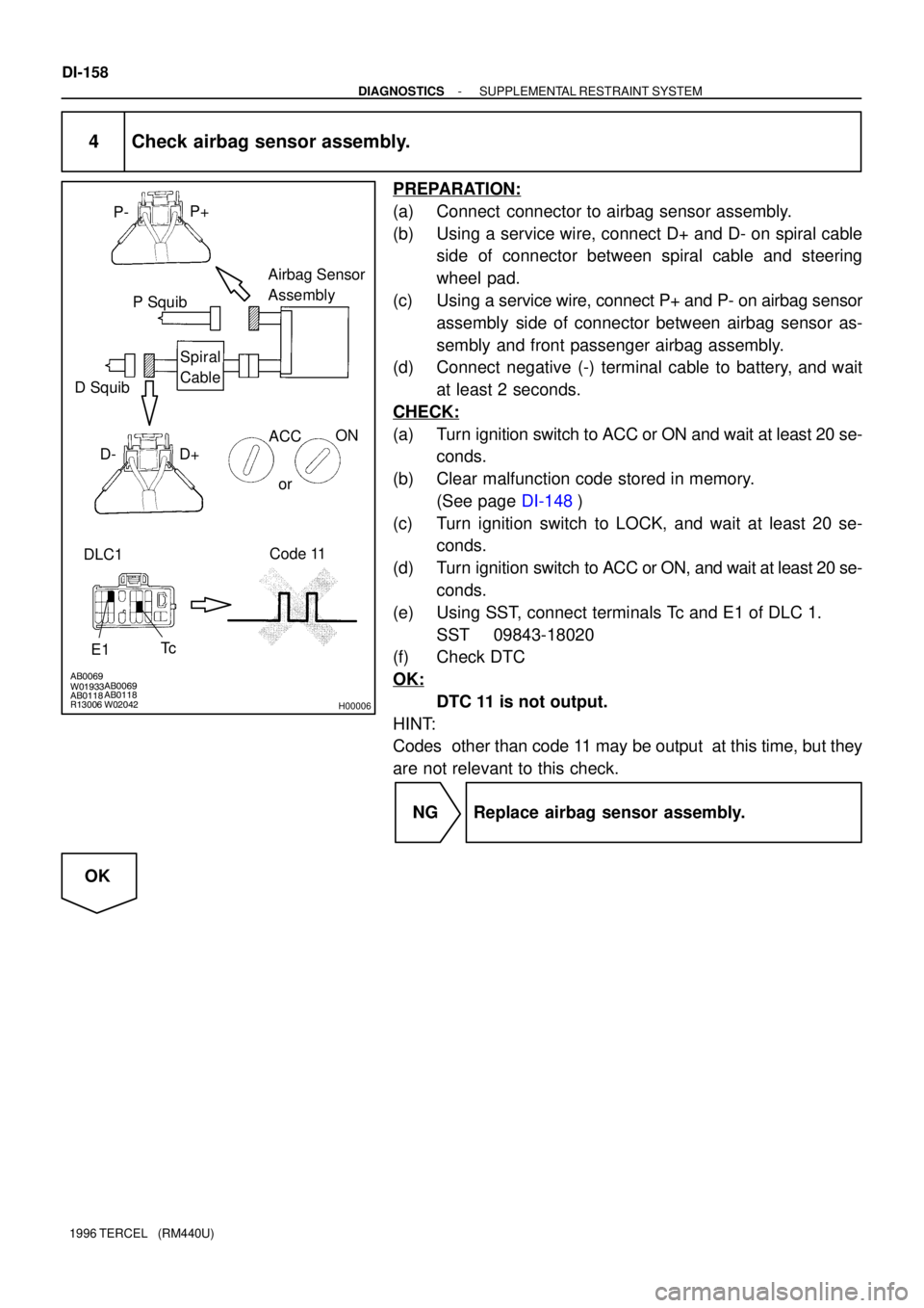
4 Check airbag sensor assembly.
PREPARATION:
(a) Connect connector to airbag sensor assembly.
(b) Using a service wire, connect D+ and D- on spiral cable
side of connector between spiral cable and steering
wheel pad.
(c) Using a service wire, connect P+ and P- on airbag sensor
assembly side of connector between airbag sensor as-
sembly and front passenger airbag assembly.
(d) Connect negative (-) terminal cable to battery, and wait
at least 2 seconds.
CHECK:
(a) Turn ignition switch to ACC or ON and wait at least 20 se-
conds.
(b) Clear malfunction code stored in memory.
(See page DI-148)
(c) Turn ignition switch to LOCK, and wait at least 20 se-
conds.
(d) Turn ignition switch to ACC or ON, and wait at least 20 se-
conds.
(e) Using SST, connect terminals Tc and E1 of DLC 1.
SST 09843-18020
(f) Check DTC
OK:
DTC 11 is not output.
HINT:
Codes other than code 11 may be output at this time, but they
are not relevant to this check.
NG Replace airbag sensor assembly.
OK