Page 1601 of 2062

Downloaded from www.Manualslib.com manuals search engine SA0HY−07
R05272
R04282
SST
− SUSPENSION AND AXLEREAR AXLE SHAFT
SA−131
1996 TOYOTA T100 (RM449U)
REMOVAL
1. REMOVE REAR WHEEL
Torque: 103 N·m (1,050 kgf·cm, 76 ft·lbf)
2. REMOVE BRAKE DRUM
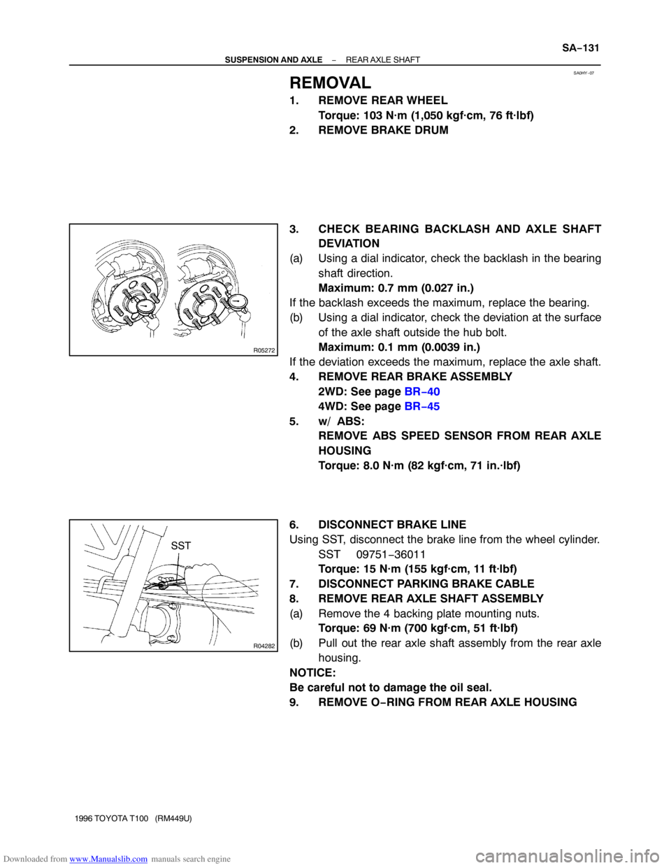
3. CHECK BEARING BACKLASH AND AXLE SHAFT
DEVIATION
(a) Using a dial indicator, check the backlash in the bearing
shaft direction.
Maximum: 0.7 mm (0.027 in.)
If the backlash exceeds the maximum, replace the bearing.
(b) Using a dial indicator, check the deviation at the surface
of the axle shaft outside the hub bolt.
Maximum: 0.1 mm (0.0039 in.)
If the deviation exceeds the maximum, replace the axle shaft.
4. REMOVE REAR BRAKE ASSEMBLY
2WD: See page BR−40
4WD: See page BR−45
5. w/ ABS:
REMOVE ABS SPEED SENSOR FROM REAR AXLE
HOUSING
Torque: 8.0 N·m (82 kgf·cm, 71 in.·lbf)
6. DISCONNECT BRAKE LINE
Using SST, disconnect the brake line from the wheel cylinder.
SST 09751−36011
Torque: 15 N·m (155 kgf·cm, 11 ft·lbf)
7. DISCONNECT PARKING BRAKE CABLE
8. REMOVE REAR AXLE SHAFT ASSEMBLY
(a) Remove the 4 backing plate mounting nuts.
Torque: 69 N·m (700 kgf·cm, 51 ft·lbf)
(b) Pull out the rear axle shaft assembly from the rear axle
housing.
NOTICE:
Be careful not to damage the oil seal.
9. REMOVE O−RING FROM REAR AXLE HOUSING
Page 1602 of 2062

Downloaded from www.Manualslib.com manuals search engine SA0HZ−01
R12297
R12298
SA0528
SST
RA0177
SST
R12254
SA−132
− SUSPENSION AND AXLEREAR AXLE SHAFT
1996 TOYOTA T100 (RM449U)
INSPECTION
1. w/ ABS:
REMOVE BEARING RETAINER (DIFFERENTIAL SIDE)
AND ABS SPEED SENSOR ROTOR
(a) Attach 4 nuts to the serration bolts and remove the serra-
tion bolts from the backing plate using a hammer.
NOTICE:
Do not reuse the nuts previously removed from the vehicle.
(b) Grind the retainer and sensor rotor surfaces using a grind-
er, then chisel them out with a chisel.
2. REMOVE SNAP RING FROM AXLE SHAFT
Using a snap ring expander, remove the snap ring.
3. REMOVE REAR AXLE SHAFT FROM BACKING
PLATE
(a) Attach 4 washers and nuts to the serration bolts, then
torque the nuts to install the serration bolts to the backing
plate.
(b) Remove the 4 nuts from the serration bolts.
(c) Position SST on the backing plate with 4 nuts.
SST 09521−25011
(d) Using a press, remove the rear axle shaft with bearing re-
tainer from the backing plate.
(e) Remove the SST.
4. INSPECT AXLE SHAFT AND FLANGE FOR RUNOUT
FOR WEAR, DAMAGE OR RUNOUT
Maximum:
Shaft runout: 2.0 mm (0.079 in.)
Flange runout: 0.1 mm (0.004 in.)
If the rear axle shaft or flange are damaged or worn, or if runout
is greater than the maximum, replace the rear axle shaft.
Page 1604 of 2062

Downloaded from www.Manualslib.com manuals search engine R04283
SST
R04284
SST
R12939
SSTBearing Side
Z17542SST 122.2 ± 1mm
(4.811 ± 0.039 in.) SA−134
− SUSPENSION AND AXLEREAR AXLE SHAFT
1996 TOYOTA T100 (RM449U)
12. INSPECT OIL SEAL (INNER SIDE)
Check for wear or damage.
13. REPLACE OIL SEAL (INNER SIDE)
(a) Using SST, remove the oil seal.
SST 09308−00010
(b) Using SST and a hammer, install a new oil seal.
SST 09950−60020 (09951−00890),
09950−70010 (09951−07150)
(c) Apply MP grease to the oil seal lip.
14. INSTALL REAR AXLE SHAFT IN BACKING PLATE
(a) Apply MP grease to the oil seal lip.
(b) Install the backing plate and bearing retainer on the rear
axle shaft.
(c) Using SST and a press, install the rear axle shaft into the
backing plate.
SST 09316−60011 (09316−00051)
(d) Using snap ring pliers, install a new snap ring.
15. w/ ABS:
INSTALL ABS SPEED SENSOR ROTOR AND
BEARING RETAINER (DIFFERENTIAL SIDE)
Using SST and a press, install a new sensor rotor and a new
bearing retainer to the axle shaft.
SST 09316−60011 (09316−00051)
Standard length: 122.2 ± 1 mm (4.811 ± 0.039 in.)
Page 1605 of 2062
Downloaded from www.Manualslib.com manuals search engine SA0I0−01
− SUSPENSION AND AXLEREAR AXLE SHAFT
SA−135
1996 TOYOTA T100 (RM449U)
INSTALLATION
Installation is in the reverse order of removal (See page SA−131).
AFTER INSTALLATION, BLEED BRAKE SYSTEM (See page BR−4), CHECK FOR LEAKS AND ABS
SPEED SENSOR SIGNAL (See page DI−321)
Page 1637 of 2062
Downloaded from www.Manualslib.com manuals search engine BR – BRAKE
BRAKE SYSTEM BR-1
TROUBLESHOOTING BR-2
BRAKE FLUID BR-4
BRAKE PEDAL BR-6
PARKING BRAKE LEVER BR-8
BRAKE MASTER CYLINDER BR-9
BRAKE BOOSTER ASSEMBLY BR-17
FRONT BRAKE PAD (2WD) BR-21
FRONT BRAKE PAD (4WD) BR-24
FRONT BRAKE CALIPER (2WD) BR-26
FRONT BRAKE CALIPER (4WD) BR-33
REAR DRUM BRAKE (2WD) BR-39
REAR DRUM BRAKE (4WD) BR-44
LEAD SENSING PROPORTIONING AND
BY-PASS VALVE (LSP & BV) BR-50
ABS ACTUATOR BR-58
FRONT SPEED SENSOR BR-64
REAR SPEED SENSOR BR-67
Page 1701 of 2062
Downloaded from www.Manualslib.com manuals search engine BR0A2−04
R14754
4WD:
2WD:
Speed Sensor
Sensor Rotor
N·m (kgf·cm, ft·lbf) : Specified torque
5.0 (51, 44 in.·lbf)
8.0 (82, 71in.·lbf)
Speed Sensor
8.0 (82, 71in.·lbf)
5.0 (51, 44 in.·lbf)
BR−64
− BRAKEFRONT SPEED SENSOR
1669 Author�: Date�:
1996 TOYOTA T100 (RM449U)
FRONT SPEED SENSOR
COMPONENTS
Page 1702 of 2062
Downloaded from www.Manualslib.com manuals search engine BR0A3−01
R07884
− BRAKEFRONT SPEED SENSOR
BR−65
1996 TOYOTA T100 (RM449U)
REMOVAL
1. DISCONNECT SPEED SENSOR CONNECTOR
2. REMOVE SPEED SENSOR
(a) 4WD:
Remove the 3 clamp bolts holding the sensor harness
from the frame, upper arm and steering knuckle.
(b) 2WD:
Remove the 2 clamp bolts holding the sensor harness
from the frame and upper arm.
Torque: 5.0 N·m (51 kgf·cm, 44 in.·lbf)
(c) Remove the speed sensor from the steering knuckle.
Torque: 8.0 N·m (82 kgf·cm, 71 in.·lbf)
Page 1703 of 2062
Downloaded from www.Manualslib.com manuals search engine BR0A4−03
BR−66
− BRAKEFRONT SPEED SENSOR
1996 TOYOTA T100 (RM449U)
INSTALLATION
Installation is reverse in the order of removal (See page BR−65).
AFTER INSTALLATION, CHECK SPEED SENSOR SIGNAL (See page DI−341)