Page 30 of 2062

Downloaded from www.Manualslib.com manuals search engine IN0379
Sensor Side
ECU Side
IN0378
Sensor SideECU Side
IN0380
Sensor SideECU Side
IN0381
Pull Lightly
Looseness of Crimping
− INTRODUCTIONHOW TO TROUBLESHOOT ECU CONTROLLED
SYSTEMSIN−27
1996 TOYOTA T100 (RM449U)
2. CONTINUITY CHECK (OPEN CIRCUIT CHECK)
(a) Disconnect the connectors at both ECU and sensor
sides.
(b) Measure the resistance between the applicable terminals
of the connectors.
HINT:
�Measure the resistance while lightly shaking the wire har-
ness vertically and horizontally.
�When tester probes are inserted into a connector, insert
the probes from the back. For waterproof connectors in
which the probes cannot be inserted from the back, be
careful not to bend the terminals when inserting the tester
probes.
3. RESISTANCE CHECK (SHORT CIRCUIT CHECK)
(a) Disconnect the connectors on both ends.
(b) Measure the resistance between the applicable terminals
of the connectors and body ground. Be sure to carry out
this check on the connectors on both ends.
Resistance: 1 MΩ or higher
HINT:
Measure the resistance while lightly shaking the wire harness
vertically and horizontally.
4. VISUAL CHECK AND CONTACT PRESSURE CHECK
(a) Disconnect the connectors at both ends.
(b) Check for rust or foreign material, etc. in the terminals of
the connectors.
(c) Check crimped portions for looseness or damage and
check if the terminals are secured in lock portion.
HINT:
The terminals should not come out when pulled lightly.
(d) Prepare a test male terminal and insert it in the female ter-
minal, then pull it out.
NOTICE:
When testing a gold−plated female terminal, always use a
gold−plated male terminal.
HINT:
When the test terminal is pulled out more easily than others,
there may be poor contact in that section.
Page 966 of 2062

Downloaded from www.Manualslib.com manuals search engine FI2553
SST
MF−2
− MFI (3RZ−FE)MFI SYSTEM
954 Author�: Date�:
1996 TOYOTA T100 (RM449U)
6. ELECTRONIC CONTROL SYSTEM
(a) Before removing SFI wiring connectors, terminals, etc.,
first disconnect the power by either turning the ignition
switch to LOCK or disconnecting the negative (−) terminal
cable from the battery.
HINT:
Always check the diagnostic trouble code before disconnecting
the battery terminal cable.
(b) When installing the battery, be especially careful not to in-
correctly connect the positive (+) and negative (−) cable
terminals.
(c) Do not permit parts to receive a severe impact during re-
moval or installation. Handle all SFI parts carefully, espe-
cially the ECM.
(d) Do not be careless during troubleshooting as there are
numerous transistor circuits and even slight terminal con-
tact can further troubles.
(e) Do not open the ECM cover.
(f) When inspecting during rainy weather, take care to pre-
vent entry of water. Also, when washing the engine
compartment, prevent water from getting on the SFI parts
and wiring connectors.
(g) Parts should be replaced as an assembly.
(h) Care is required when pulling out and inserting wiring con-
nectors.
(1) Release the lock and pull out the connector, pulling
on the connectors.
(2) Fully insert the connector and check that it is locked.
(i) When inspecting a connector with a volt/ohmmeter.
(1) Carefully take out the water−proofing rubber if it is
a water−proof type connector.
(2) Insert the test probe into the connector from wiring
side when checking the continuity, amperage or
voltage.
(3) Do not apply unnecessary force to the terminal.
(4) After checking, install the water−proofing rubber on
the connector securely.
(5) Use SST for inspection or test of the injector or its
wiring connector.
SST 09842−30070
Page 1021 of 2062
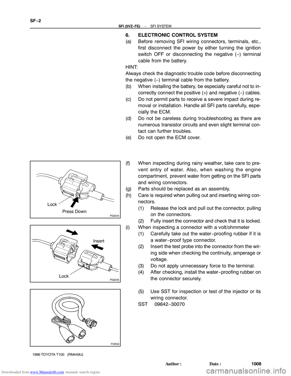
Downloaded from www.Manualslib.com manuals search engine P03244Press Down Lock
P03245LockInsert
FI2553
SF−2
− SFI (5VZ−FE)SFI SYSTEM
1008 Author�: Date�:
1996 TOYOTA T100 (RM449U)
6. ELECTRONIC CONTROL SYSTEM
(a) Before removing SFI wiring connectors, terminals, etc.,
first disconnect the power by either turning the ignition
switch OFF or disconnecting the negative (−) terminal
cable from the battery.
HINT:
Always check the diagnostic trouble code before disconnecting
the negative (−) terminal cable from the battery.
(b) When installing the battery, be especially careful not to in-
correctly connect the positive (+) and negative (−) cables.
(c) Do not permit parts to receive a severe impact during re-
moval or installation. Handle all SFI parts carefully, espe-
cially the ECM.
(d) Do not be careless during troubleshooting as there are
numerous transistor circuits and even slight terminal con-
tact can further troubles.
(e) Do not open the ECM cover.
(f) When inspecting during rainy weather, take care to pre-
vent entry of water. Also, when washing the engine
compartment, prevent water from getting on the SFI parts
and wiring connectors.
(g) Parts should be replaced as an assembly.
(h) Care is required when pulling out and inserting wiring con-
nectors.
(1) Release the lock and pull out the connector, pulling
on the connectors.
(2) Fully insert the connector and check that it is locked.
(i) When inspecting a connector with a volt/ohmmeter
(1) Carefully take out the water−proofing rubber if it is
a water−proof type connector.
(2) Insert the test probe into the connector from the wir-
ing side when checking the continuity, amperage or
voltage.
(3) Do not apply unnecessary force to the terminal.
(4) After checking, install the water−proofing rubber on
the connector securely.
(5) Use SST for inspection or test of the injector or its
wiring connector.
SST 09842−30070
Page 1166 of 2062

Downloaded from www.Manualslib.com manuals search engine IG0LA−01
IG−8
− IGNITION (3RZ−FE)DISTRIBUTOR
1996 TOYOTA T100 (RM449U)
DISASSEMBLY
1. REMOVE ROTOR
2. REMOVE IGNITION COIL DUST COVER
(a) Remove the dust cover.
(b) Remove the dust proof packing.
HINT:
At the time of reassembly, please refer to the following item. Use
new dust proof packing.
3. REMOVE IGNITION COIL
(a) Remove the 2 nuts, and disconnect the 3 wires from the
ignition coil terminals.
NOTICE:
At the time of reassembly, please refer to the following
items.
�When connecting the wires to the ignition coil, insert
the properly into the groove found on the side of the
ignition coil.
�Be sure the wire do not contact with signal rotor or
distributor housing.
(b) Remove the 4 screws and ignition coil.
NOTICE:
At the time of reassembly, please refer to the following
items.
Apply seal packing to the ignition coil installing serface of
the housing, as shown in the illustration.
Seal packing: Part No. 08826 − 00080 or equivalent