Page 1543 of 2062
Downloaded from www.Manualslib.com manuals search engine SA0GD−01
R03309
W00406
− SUSPENSION AND AXLEFRONT SHOCK ABSORBER (2WD)
SA−73
1996 TOYOTA T100 (RM449U)
REMOVAL
1. REMOVE FRONT WHEEL
Torque: 103 N·m (1,050 kgf·cm, 76 ft·lbf)
2. REMOVE SHOCK ABSORBER
(a) Remove the 2 bolts and disconnect the shock absorber
lower side from the lower suspension arm.
Torque: 18 N·m (185 kgf·cm, 13 ft·lbf)
(b) Hold the shock absorber and remove the set nut, 2 retain-
ers, cushion and shock absorber.
Torque: 25 N·m (250 kgf·cm, 18 ft·lbf)
(c) Remove the 2 retainers and cushion from the shock ab-
sorber.
Page 1562 of 2062
Downloaded from www.Manualslib.com manuals search engine SA0GW−07
R04506
FA0126
SA−92
− SUSPENSION AND AXLEFRONT UPPER SUSPENSION ARM (2WD)
1996 TOYOTA T100 (RM449U)
REMOVAL
1. REMOVE FRONT WHEEL
Torque: 103 N·m (1,050 kgf·cm, 76 ft·lbf)
2. REMOVE BRAKE CALIPER (See page BR−27)
3. w/ ABS:
DISCONNECT ABS SPEED SENSOR WIRE FROM UP-
PER SUSPENSION ARM
Torque:8.0 N·m (82 kgf·cm, 71 in.·lbf)
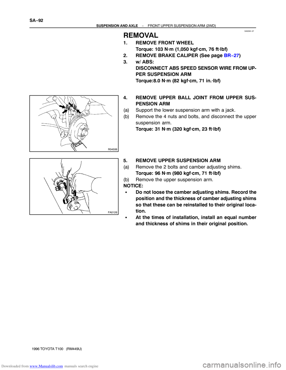
4. REMOVE UPPER BALL JOINT FROM UPPER SUS-
PENSION ARM
(a) Support the lower suspension arm with a jack.
(b) Remove the 4 nuts and bolts, and disconnect the upper
suspension arm.
Torque: 31 N·m (320 kgf·cm, 23 ft·lbf)
5. REMOVE UPPER SUSPENSION ARM
(a) Remove the 2 bolts and camber adjusting shims.
Torque: 96 N·m (980 kgf·cm, 71 ft·lbf)
(b) Remove the upper suspension arm.
NOTICE:
�Do not loose the camber adjusting shims. Record the
position and the thickness of camber adjusting shims
so that these can be reinstalled to their original loca-
tion.
�At the times of installation, install an equal number
and thickness of shims in their original position.
Page 1566 of 2062
Downloaded from www.Manualslib.com manuals search engine SA0H0−02
R04248
R04249
R04254
SA−96
− SUSPENSION AND AXLEFRONT UPPER SUSPENSION ARM (4WD)
1996 TOYOTA T100 (RM449U)
REMOVAL
1. REMOVE FRONT WHEEL
Torque: 103 N·m (1,050 kgf·cm, 76 ft·lbf)
2. w/ ABS:
DISCONNECT ABS SPEED SENSOR WIRE FROM
UPPER SUSPENSION ARM
Torque:8.0 N·m (82 kgf·cm, 71 in.·lbf)
3. REMOVE TORSION BAR SPRING (See page SA−86)
4. REMOVE UPPER BALL JOINT FROM UPPER
SUSPENSION ARM
NOTICE:
Make sure the steering knuckle is positively secured, as
shown, before removing upper ball joint from upper sus-
pension arm.
(a) Support the lower suspension arm with a jack.
(b) Remove the 4 nuts and disconnect the upper suspension
arm from the steering knuckle.
Torque: 33 N·m (340 kgf·cm, 25 ft·lbf)
(c) Remove the 3 bolts and remove the upper suspension
arm from frame.
Torque: 178 N·m (1,810 kgf·cm, 131 ft·lbf)
Page 1578 of 2062
Downloaded from www.Manualslib.com manuals search engine SA0HC−01
R04507
SA−108
− SUSPENSION AND AXLEFRONT UPPER BALL JOINT (2WD)
1996 TOYOTA T100 (RM449U)
REMOVAL
1. REMOVE FRONT WHEEL
Torque: 103 N·m (1,050 kgf·cm, 76 ft·lbf)
2. REMOVE STEERING KNUCKLE (See page SA−16)
3. REMOVE UPPER BALL JOINT
(a) Remove the 4 nuts and bolts.
Torque: 31 N·m (320 kgf·cm, 23 ft·lbf)
(b) Remove the upper ball joint from the upper suspension
arm.
Page 1594 of 2062
Downloaded from www.Manualslib.com manuals search engine SA0HS−01
R04505
R05271
SA−124
− SUSPENSION AND AXLEFRONT STABILIZER BAR (2WD)
1996 TOYOTA T100 (RM449U)
REMOVAL
1. REMOVE FRONT WHEEL
Torque: 103 N·m (1,050 kgf·cm, 76 ft·lbf)
2. REMOVE STABILIZER BAR
(a) Remove the nut, 3 retainers, 2 cushions and stabilizer bar
from the lower suspension arm.
Torque: 13 N·m (130 kgf·cm, 9 ft·lbf)
(b) Remove the nut, 2 cushions, 2 retainers and disconnect
the stabilizer bar.
Torque: 13 N·m (130 kgf·cm, 9 ft·lbf)
(c) Employ the same manner described above to the other
side.
(d) Remove the 4 bolts, stabilizer bar brackets, bushings and
remove the stabilizer bar.
Torque: 30 N·m (306 kgf·cm, 22 ft·lbf)
Page 1632 of 2062
Downloaded from www.Manualslib.com manuals search engine SA0IE−01
W00476
W00477
R04379
R04380
SA−162
− SUSPENSION AND AXLEREAR LEAF SPRING
1996 TOYOTA T100 (RM449U)
REMOVAL
1. SUPPORT BODY
(a) Jack up and support the body on the stands.
(b) Lower the axle housing until the leaf spring tension is free,
and keep it at this position.
2. REMOVE REAR WHEEL
Torque: 103 N·m (1,050 kgf·cm, 76 ft·lbf)
3. 4WD:
DISCONNECT PARKING BRAKE CABLE
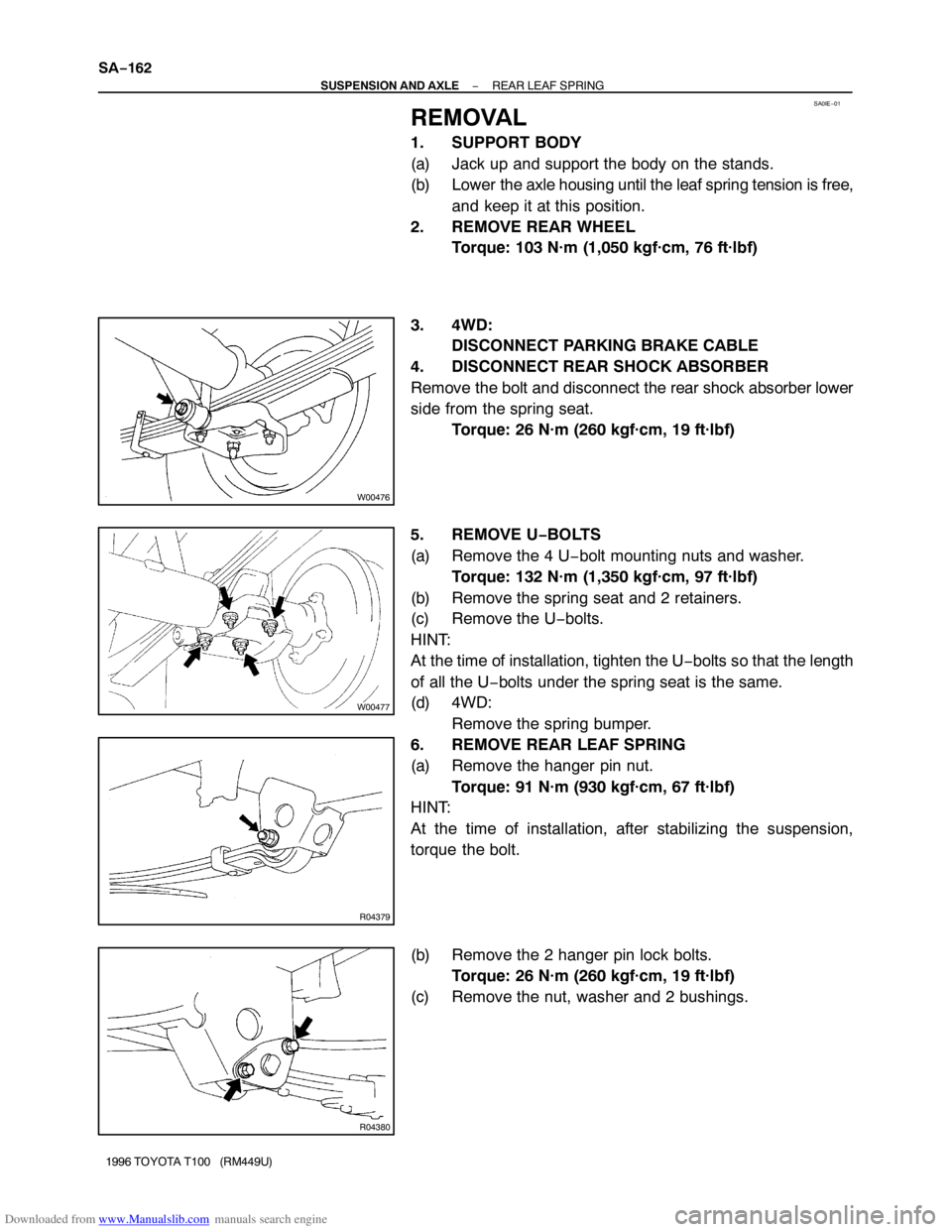
4. DISCONNECT REAR SHOCK ABSORBER
Remove the bolt and disconnect the rear shock absorber lower
side from the spring seat.
Torque: 26 N·m (260 kgf·cm, 19 ft·lbf)
5. REMOVE U−BOLTS
(a) Remove the 4 U−bolt mounting nuts and washer.
Torque: 132 N·m (1,350 kgf·cm, 97 ft·lbf)
(b) Remove the spring seat and 2 retainers.
(c) Remove the U−bolts.
HINT:
At the time of installation, tighten the U−bolts so that the length
of all the U−bolts under the spring seat is the same.
(d) 4WD:
Remove the spring bumper.
6. REMOVE REAR LEAF SPRING
(a) Remove the hanger pin nut.
Torque: 91 N·m (930 kgf·cm, 67 ft·lbf)
HINT:
At the time of installation, after stabilizing the suspension,
torque the bolt.
(b) Remove the 2 hanger pin lock bolts.
Torque: 26 N·m (260 kgf·cm, 19 ft·lbf)
(c) Remove the nut, washer and 2 bushings.
Page 1635 of 2062
Downloaded from www.Manualslib.com manuals search engine R04069
W00479
W00480
− SUSPENSION AND AXLEREAR LEAF SPRING
SA−165
1996 TOYOTA T100 (RM449U)
(e) Bend the spring clip.
Using a hammer, bend the spring clip into the position.
3. REPLACE SPRING BUMPER
(a) Remove rear wheel.
Torque: 103 N·m (1,050 kgf·cm, 76 ft·lbf)
(b) Remove spring bumper.
(1) STD 0.5 ton, Extra cab:
Remove the 2 bolts, spring bumper and spacers.
Torque: 29 N·m (300 kgf·cm, 22 ft·lbf)
HINT:
At the time of installation, install the spacers, as shown in the
illustration.
(2) STD 1.0 ton:
Remove the 2 bolts, spring bumper and bumper
block spacers.
Torque: 29 N·m (300 kgf·cm, 22 ft·lbf)
HINT:
At the time of installation, install the spacers, as shown in the
illustration.
Page 1660 of 2062
Downloaded from www.Manualslib.com manuals search engine R05057
R05256
− BRAKEFRONT BRAKE PAD (2WD)
BR−23
1996 TOYOTA T100 (RM449U)
(d) Install the 2 pads so that the wear indicator plate is facing
underneath.
NOTICE:
Do not allow oil or grease on the rubbing face.
8. INSTALL CALIPER
(a) Draw out a small amount of brake fluid from the reservoir.
(b) Press in piston with a hammer handle or equivalent.
HINT:
If the piston is difficult to push in, loosen the bleeder plug and
push in the piston while letting some brake fluid escape.
(c) Insert the brake caliper carefully so the boot is not
wedged.
(d) Install and torque the installation bolts.
Torque:
1 ton: 39 N·m (400 kgf·cm, 29 ft·lbf)
Torque:
0.5 ton: 36 N·m (370 kgf·cm, 27 ft·lbf)
9. INSTALL FRONT WHEEL
10. CHECK THAT FLUID LEVEL IS AT MAX LINE


