Page 1278 of 2062
Downloaded from www.Manualslib.com manuals search engine CL02L−01
Q06647
5VZ−FE 3RZ−FE
SST Flywheel
Side
Q06958
1,4
7
3
62,58 Matchmarks
Q06641
SST
Z00762
Q06642
− CLUTCHCLUTCH UNIT
CL−19
1996 TOYOTA T100 (RM449U)
INSTALLATION
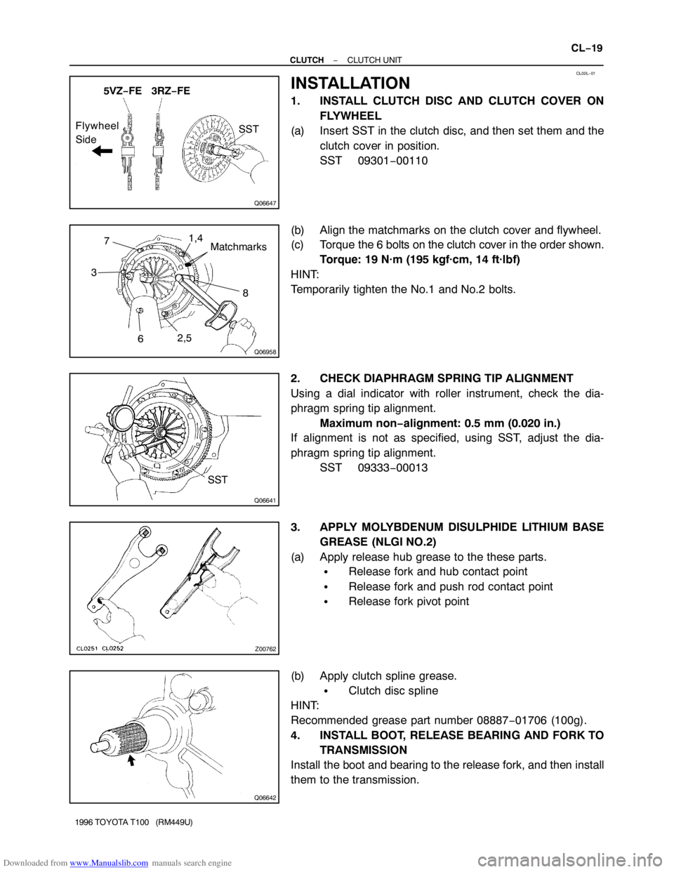
1. INSTALL CLUTCH DISC AND CLUTCH COVER ON
FLYWHEEL
(a) Insert SST in the clutch disc, and then set them and the
clutch cover in position.
SST 09301−00110
(b) Align the matchmarks on the clutch cover and flywheel.
(c) Torque the 6 bolts on the clutch cover in the order shown.
Torque: 19 N·m (195 kgf·cm, 14 ft·lbf)
HINT:
Temporarily tighten the No.1 and No.2 bolts.
2. CHECK DIAPHRAGM SPRING TIP ALIGNMENT
Using a dial indicator with roller instrument, check the dia-
phragm spring tip alignment.
Maximum non−alignment: 0.5 mm (0.020 in.)
If alignment is not as specified, using SST, adjust the dia-
phragm spring tip alignment.
SST 09333−00013
3. APPLY MOLYBDENUM DISULPHIDE LITHIUM BASE
GREASE (NLGI NO.2)
(a) Apply release hub grease to the these parts.
�Release fork and hub contact point
�Release fork and push rod contact point
�Release fork pivot point
(b) Apply clutch spline grease.
�Clutch disc spline
HINT:
Recommended grease part number 08887−01706 (100g).
4. INSTALL BOOT, RELEASE BEARING AND FORK TO
TRANSMISSION
Install the boot and bearing to the release fork, and then install
them to the transmission.
Page 1481 of 2062
Downloaded from www.Manualslib.com manuals search engine SA3213
Front AB
D
C
FA0829FA0828F01734
Decrease
Increase
Decrease Increase Front Adjusting Cam
Rear Adjusting Cam
R08116
FA0017
Front
A = B AB
− SUSPENSION AND AXLEFRONT WHEEL ALIGNMENT (4WD)
SA−11
1450 Author�: Date�:
1996 TOYOTA T100 (RM449U)
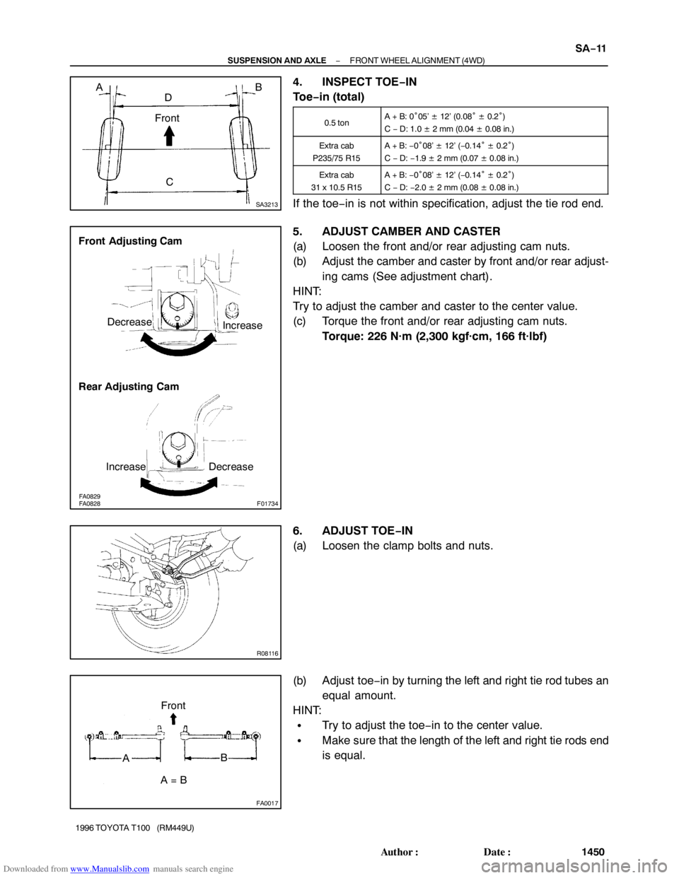
4. INSPECT TOE−IN
To e−in (total)
0.5 tonA + B: 0°05’ ± 12’ (0.08° ± 0.2°)
C − D: 1.0 ± 2 mm (0.04 ± 0.08 in.)
Extra cab
P235/75 R15A + B: −0°08’ ± 12’ (−0.14° ± 0.2°)
C − D: −1.9 ± 2 mm (0.07 ± 0.08 in.)
Extra cab
31 x 10.5 R15A + B: −0°08’ ± 12’ (−0.14° ± 0.2°)
C − D: −2.0 ± 2 mm (0.08 ± 0.08 in.)
If the toe−in is not within specification, adjust the tie rod end.
5. ADJUST CAMBER AND CASTER
(a) Loosen the front and/or rear adjusting cam nuts.
(b) Adjust the camber and caster by front and/or rear adjust-
ing cams (See adjustment chart).
HINT:
Try to adjust the camber and caster to the center value.
(c) Torque the front and/or rear adjusting cam nuts.
Torque: 226 N·m (2,300 kgf·cm, 166 ft·lbf)
6. ADJUST TOE−IN
(a) Loosen the clamp bolts and nuts.
(b) Adjust toe−in by turning the left and right tie rod tubes an
equal amount.
HINT:
�Try to adjust the toe−in to the center value.
�Make sure that the length of the left and right tie rods end
is equal.
Page 1482 of 2062
Downloaded from www.Manualslib.com manuals search engine FA0927
Front
FA0018
Front
A: Inside
B: Outside ABBA
R08117
SA−12
− SUSPENSION AND AXLEFRONT WHEEL ALIGNMENT (4WD)
1451 Author�: Date�:
1996 TOYOTA T100 (RM449U)
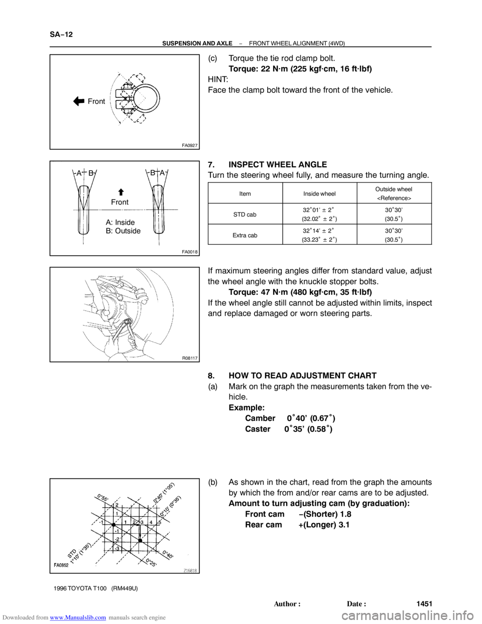
(c) Torque the tie rod clamp bolt.
Torque: 22 N·m (225 kgf·cm, 16 ft·lbf)
HINT:
Face the clamp bolt toward the front of the vehicle.
7. INSPECT WHEEL ANGLE
Turn the steering wheel fully, and measure the turning angle.
ItemInside wheelOutside wheel
STD cab32°01’ ± 2°
(32.02° ± 2°)30°30’
(30.5°)
Extra cab32°14’ ± 2°
(33.23° ± 2°)30°30’
(30.5°)
If maximum steering angles differ from standard value, adjust
the wheel angle with the knuckle stopper bolts.
Torque: 47 N·m (480 kgf·cm, 35 ft·lbf)
If the wheel angle still cannot be adjusted within limits, inspect
and replace damaged or worn steering parts.
8. HOW TO READ ADJUSTMENT CHART
(a) Mark on the graph the measurements taken from the ve-
hicle.
Example:
Camber 0°40’ (0.67°)
Caster 0°35’ (0.58°)
(b) As shown in the chart, read from the graph the amounts
by which the from and/or rear cams are to be adjusted.
Amount to turn adjusting cam (by graduation):
Front cam −(Shorter) 1.8
Rear cam +(Longer) 3.1
Page 1486 of 2062

Downloaded from www.Manualslib.com manuals search engine SA0FI−01
W00397
R04268
FA0026
SST SA−16
− SUSPENSION AND AXLEFRONT AXLE HUB (2WD)
1996 TOYOTA T100 (RM449U)
REMOVAL
1. REMOVE FRONT WHEEL
2. w/ ABS:
DISCONNECT ABS SPEED SENSOR FROM
STEERING KNUCKLE
3. REMOVE BRAKE CALIPER
(a) Remove the 2 brake caliper set bolts.
(b) Support the brake caliper securely.
4. CHECK AXLE HUB BEARING BACKLASH
(a) Remove the cap, cotter pin and lock cap.
(b) Using a dial indicator near the center of the axle hub and
check the backlash in the bearing shaft direction.
Maximum: 0.05 mm (0.0020 in.)
If the backlash is not within the specification replace the bear-
ing.
5. REMOVE AXLE HUB WITH DISC
(a) Using a 30 mm socket, remove the nut.
(b) Remove the axle hub with the disc together with the outer
bearing from the steering knuckle.
NOTICE:
Be careful not to drop the outer bearing.
6. REMOVE OIL SEAL AND INNER BEARING
(a) Using a screwdriver, pry out the oil seal.
NOTICE:
Be careful not to damage the ABS speed sensor rotor.
(b) Remove the inner bearing from the axle hub.
7. REMOVE DUST COVER
Remove the 3 bolts and dust cover.
8. DISCONNECT KNUCKLE ARM FROM STEERING
KNUCKLE
Remove the 2 bolts and disconnect the knuckle arm from the
steering knuckle.
9. REMOVE STEERING KNUCKLE
(a) Support the lower suspension arm with a jack.
(b) Remove the upper and lower cotter pins.
(c) Remove the upper and lower nuts.
(d) Using SST, disconnect the steering knuckle from the up-
per and lower ball joints.
SST 09628−62011
(e) Remove the steering knuckle.
Page 1491 of 2062
Downloaded from www.Manualslib.com manuals search engine R04258
− SUSPENSION AND AXLEFRONT AXLE HUB (2WD)
SA−21
1996 TOYOTA T100 (RM449U)
(f) Using a dial indicator, measure the hub bearing backlash.
Maximum: 0.05 mm (0.0020 in.)
9. INSTALL LOCK CAP, COTTER PIN AND GREASE CAP
(a) Install the lock cap and a new cotter pin.
(b) Install the grease cap.
10. INSTALL BRAKE CALIPER
Install the 2 brake caliper set bolts.
Torque: 108 N·m (1,100 kgf·cm, 80 ft·lbf)
11. w/ ABS:
CONNECT ABS SPEED SENSOR TO STEERING
KNUCKLE
Torque: 8.0 N·m (82 kgf·cm, 71 in.·lbf)
12. INSTALL FRONT WHEEL
Torque: 103 N·m (1,050 kgf·cm, 76 ft·lbf)
13. CHECK FRONT WHEEL ALIGNMENT
(See page SA−7)
14. w/ ABS:
CHECK ABS SPEED SENSOR SIGNAL
(See page DI−321)
Page 1493 of 2062

Downloaded from www.Manualslib.com manuals search engine SA0FN−01
W00399
SA0326
R04292
SST
− SUSPENSION AND AXLEFRONT AXLE HUB (4WD)
SA−23
1996 TOYOTA T100 (RM449U)
REMOVAL
1. REMOVE FRONT WHEEL
2. w/ ABS:
DISCONNECT ABS SPEED SENSOR FROM
STEERING KNUCKLE
3. REMOVE BRAKE CALIPER
(a) Remove the 2 bolts and disconnect the knuckle arm with
brake line bracket from the steering knuckle.
(b) Remove the 2 brake caliper set bolts.
(c) Support the brake caliper securely.
4. REMOVE FLANGE
(a) Remove the grease cap from the flange.
(b) Remove the bolt.
(c) Remove the 6 mounting nuts and washers.
(d) Using a brass bar and hammer, tap on the bolts head and
remove the 6 cone washers.
(e) Install and tighten the 2 bolts and remove the flange.
(f) Remove the gasket.
5. REMOVE AXLE HUB WITH DISC
(a) Using a screwdriver, release the lock washer.
(b) Using SST, remove the lock nut.
SST 09607−60020
(c) Remove the lock washer and adjusting nut.
(d) Remove the claw washer.
(e) Remove the axle hub with the disc together with the outer
bearing.
NOTICE:
Be careful not to damage the ABS speed sensor rotor.
6. REMOVE OIL SEAL AND INNER BEARING
(a) Using a screwdriver, pry out the oil seal.
(b) Remove the inner bearing from the hub.
Page 1496 of 2062
Downloaded from www.Manualslib.com manuals search engine R12259
90°
R11765
Sealant SA−26
− SUSPENSION AND AXLEFRONT AXLE HUB (4WD)
1996 TOYOTA T100 (RM449U)
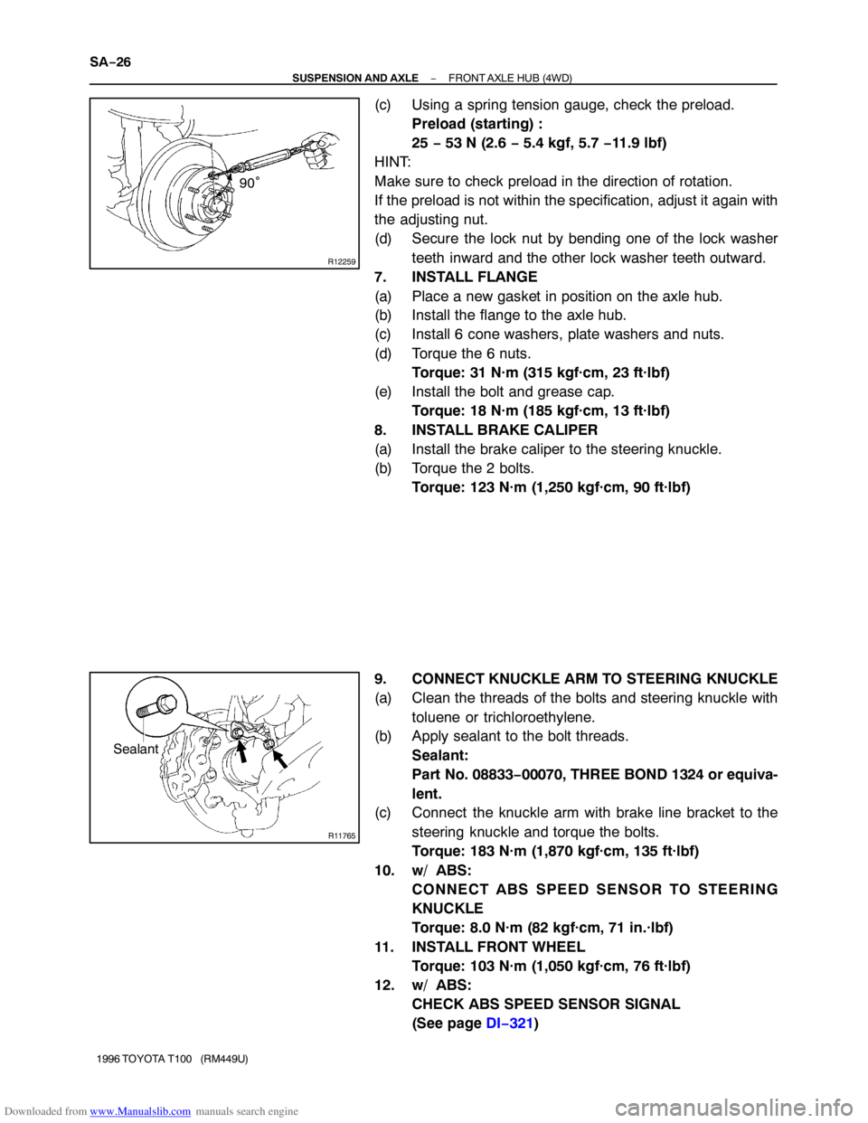
(c) Using a spring tension gauge, check the preload.
Preload (starting) :
25 − 53 N (2.6 − 5.4 kgf, 5.7 −11.9 lbf)
HINT:
Make sure to check preload in the direction of rotation.
If the preload is not within the specification, adjust it again with
the adjusting nut.
(d) Secure the lock nut by bending one of the lock washer
teeth inward and the other lock washer teeth outward.
7. INSTALL FLANGE
(a) Place a new gasket in position on the axle hub.
(b) Install the flange to the axle hub.
(c) Install 6 cone washers, plate washers and nuts.
(d) Torque the 6 nuts.
Torque: 31 N·m (315 kgf·cm, 23 ft·lbf)
(e) Install the bolt and grease cap.
Torque: 18 N·m (185 kgf·cm, 13 ft·lbf)
8. INSTALL BRAKE CALIPER
(a) Install the brake caliper to the steering knuckle.
(b) Torque the 2 bolts.
Torque: 123 N·m (1,250 kgf·cm, 90 ft·lbf)
9. CONNECT KNUCKLE ARM TO STEERING KNUCKLE
(a) Clean the threads of the bolts and steering knuckle with
toluene or trichloroethylene.
(b) Apply sealant to the bolt threads.
Sealant:
Part No. 08833−00070, THREE BOND 1324 or equiva-
lent.
(c) Connect the knuckle arm with brake line bracket to the
steering knuckle and torque the bolts.
Torque: 183 N·m (1,870 kgf·cm, 135 ft·lbf)
10. w/ ABS:
CONNECT ABS SPEED SENSOR TO STEERING
KNUCKLE
Torque: 8.0 N·m (82 kgf·cm, 71 in.·lbf)
11. INSTALL FRONT WHEEL
Torque: 103 N·m (1,050 kgf·cm, 76 ft·lbf)
12. w/ ABS:
CHECK ABS SPEED SENSOR SIGNAL
(See page DI−321)
Page 1497 of 2062
Downloaded from www.Manualslib.com manuals search engine SA0FQ−01
Z14480
Matchmarks
R03423
R03424
− SUSPENSION AND AXLEFRONT WHEEL HUB BOLT (2WD)
SA−27
1466 Author�: Date�:
1996 TOYOTA T100 (RM449U)
FRONT WHEEL HUB BOLT (2WD)
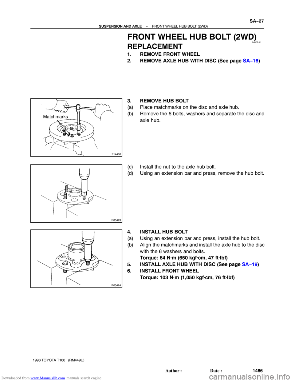
REPLACEMENT
1. REMOVE FRONT WHEEL
2. REMOVE AXLE HUB WITH DISC (See page SA−16)
3. REMOVE HUB BOLT
(a) Place matchmarks on the disc and axle hub.
(b) Remove the 6 bolts, washers and separate the disc and
axle hub.
(c) Install the nut to the axle hub bolt.
(d) Using an extension bar and press, remove the hub bolt.
4. INSTALL HUB BOLT
(a) Using an extension bar and press, install the hub bolt.
(b) Align the matchmarks and install the axle hub to the disc
with the 6 washers and bolts.
Torque: 64 N·m (650 kgf·cm, 47 ft·lbf)
5. INSTALL AXLE HUB WITH DISC (See page SA−19)
6. INSTALL FRONT WHEEL
Torque: 103 N·m (1,050 kgf·cm, 76 ft·lbf)