Page 1371 of 2062
Downloaded from www.Manualslib.com manuals search engine AT022−06
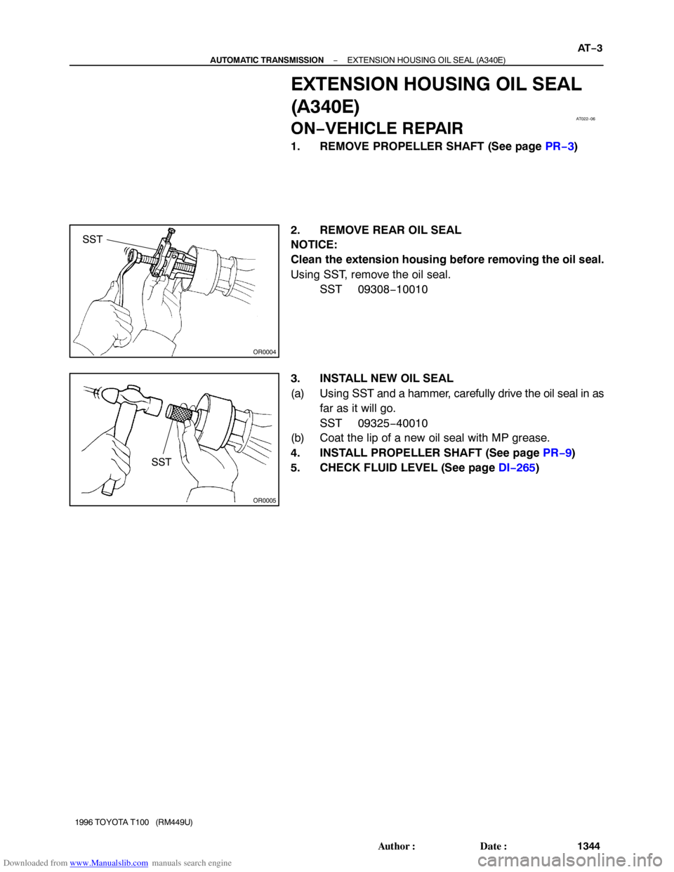
OR0004
SST
OR0005
SST
− AUTOMATIC TRANSMISSIONEXTENSION HOUSING OIL SEAL (A340E)
AT−3
1344 Author�: Date�:
1996 TOYOTA T100 (RM449U)
EXTENSION HOUSING OIL SEAL
(A340E)
ON−VEHICLE REPAIR
1. REMOVE PROPELLER SHAFT (See page PR−3)
2. REMOVE REAR OIL SEAL
NOTICE:
Clean the extension housing before removing the oil seal.
Using SST, remove the oil seal.
SST 09308−10010
3. INSTALL NEW OIL SEAL
(a) Using SST and a hammer, carefully drive the oil seal in as
far as it will go.
SST 09325−40010
(b) Coat the lip of a new oil seal with MP grease.
4. INSTALL PROPELLER SHAFT (See page PR−9)
5. CHECK FLUID LEVEL (See page DI−265)
Page 1379 of 2062
 SWITCH
AT−11
1352 Author�: Date�:
1996 TOYOTA T100 (RM449U)
PARK/NE")
Downloaded from www.Manualslib.com manuals search engine Q07624
AT01Y−01
− AUTOMATIC TRANSMISSIONPARK/NEUTRAL POSITION (PNP) SWITCH
AT−11
1352 Author�: Date�:
1996 TOYOTA T100 (RM449U)
PARK/NEUTRAL POSITION (PNP)
SWITCH
ON−VEHICLE REPAIR
1. DISCONNECT OIL COOLER PIPES
(See page A340E AT−28, A340F AT−34)
2. REMOVE PARK/NEUTRAL POSITION SWITCH
(a) Disconnect the connector.
(b) Pry off the lock washer and remove the nut.
(c) Remove the bolt and park/neutral position switch.
3. INSTALL PARK/NEUTRAL POSITION SWITCH
(a) Install the park/neutral position switch and bolt.
Torque: 13 N·m (130 kgf·cm, 9 ft·lbf)
(b) Install a new lock plate and the nut.
Torque: 3.9 N·m (40 kgf·cm, 35 in.·lbf)
(c) Bend claws on the lock plate to fix the nut.
(d) Connect the connector.
(e) Check that the engine can be started with the shift lever
only in the N or P position, but not in other positions.
If not as stated above, carry out the adjustment procedure.
(See page DI−265)
4. CONNECT OIL COOLER PIPES
(See page A340E AT−28, A340F AT−34)
5. TEST DRIVE VEHICLE
Page 1382 of 2062

AT1369
Z18882
AB
BA (A340E Only)
B
Z14778
A
B
A
B B
B A
A AT−14
− AUTOMATIC TRANSMISSIONVALVE BODY ASSEM")
Downloaded from www.Manualslib.com manuals search engine Z14779
Z18882
A
BB
BA (A340E Only)
AT1369
Z18882
AB
BA (A340E Only)
B
Z14778
A
B
A
B B
B A
A AT−14
− AUTOMATIC TRANSMISSIONVALVE BODY ASSEMBLY
1355 Author�: Date�:
1996 TOYOTA T100 (RM449U)
8. A340F:
REMOVE OIL PIPE
Pry up both pipe ends with a large screwdriver and remove the
pipe.
9. REMOVE VALVE BODY
(a) Remove the 17 (or 16) bolts.
Bolt length:
Bolt A: 23 mm (0.91 in.)
Bolt B: 32 mm (1.26 in.)
(b) Disconnect the throttle cable from the cam.
(c) Remove the valve body.
NOTICE:
Be careful not to drop the check ball body and spring.
10. INSTALL VALVE BODY
(a) Align the groove of the manual valve with the pin of the
lever.
(b) Connect the throttle cable cam.
(c) Check the springs into the accumulator pistons are
installed correctly.
(d) Install the 17 (or 16) bolts.
Torque: 10 N·m (100 kgf·cm, 7 ft·lbf)
Bolt length:
Bolt A: 23 mm (0.91 in.)
Bolt B: 32 mm (1.26 in.)
11. A340E:
INSTALL OIL PIPE
Using a plastic hammer, install the 2 pipes into the position, as
shown in the illustration.
NOTICE:
Be careful not to bend or damage the pipes.
Page 1384 of 2062
Downloaded from www.Manualslib.com manuals search engine AT1362
Seal Breadth
2 − 3 mm (0.08 − 0.12 in.)
Q07625
AT−16
− AUTOMATIC TRANSMISSIONVALVE BODY ASSEMBLY
1357 Author�: Date�:
1996 TOYOTA T100 (RM449U)
16. INSTALL OIL PAN
(a) A340E:
Install the 4 magnets.
(b) A340F:
Install the 6 magnets.
(c) Remove any packing material and be careful not to drop
oil on the contacting surfaces of the transmission case
and oil pan.
(d) Apply FIPG to the oil pan, as shown in the illustraiton.
FIPG: Part No. 08826−00090, THREE BOND 1281 or
equivalent
(e) Install the oil pan with the 19 bolts.
Torque: 7.4 N·m (75 kgf·cm, 65 in.·lbf)
17. INSTALL DRAIN PLUG
Torque: 20 N·m (205 kgf·cm, 15 ft·lbf)
18. FILL FLUID AND CHECK FLUID
Page 1410 of 2062
Downloaded from www.Manualslib.com manuals search engine TR01Q−01
TR−2
− TRANSFERTROUBLESHOOTING
1382 Author�: Date�:
1996 TOYOTA T100 (RM449U)
TROUBLESHOOTING
PROBLEM SYMPTOMS TABLE
Use the table below to help you find the cause of the problem. The numbers indicate the priority of the likely
cause of the problem. Check each part in order. If necessary, replace these parts.
SymptomSuspect AreaSee page
Noise
1. Oil (Level low)
2. Oil (Wrong)
3. Transfer faulty−
−
TR−5
Oil leakage
1. Oil (Level too high)
2. Gasket (Damaged)
3. Oil seal (Worn or damaged)
4. O−ring (Worn or damaged)−
−
TR−36
TR−36
Tight corner brakingCenter differential or transfer faultyTR−5
Page 1415 of 2062

DISASSEMBLY
1. REMOVE SPEEDOMETER DRIVEN")
Downloaded from www.Manualslib.com manuals search engine TR0CZ−01
TF0629
TF0447
Q09400
FIPG
− TRANSFERTRANSFER ASSEMBLY
TR−7
1996 TOYOTA T100 (RM449U)
DISASSEMBLY
1. REMOVE SPEEDOMETER DRIVEN GEAR
Torque: 11 N·m (115 kgf·cm, 8 ft·lbf)
2. REMOVE TRANSFER INDICATOR SWITCH
Torque: 37 N·m (380 kgf·cm, 27 ft·lbf)
3. A/T:
REMOVE TRANSFER L4 AND NEUTRAL POSITION
SWITCH
Torque: 37 N·m (380 kgf·cm, 27 ft·lbf)
HINT:
At the time of installation, check the following items.
�Check to see that the input shaft and output shafts rotate
smoothly.
�Check to see that shifting can be made smoothly to all
position.
4. A/T:
REMOVE SHIFT GEAR HEAD NO.1 AND NO.2
(a) Using a pin punch and hammer, drive out the 2 slotted
spring pins.
(b) Remove the 2 shift gear heads.
5. REMOVE FRONT RETAINER
(a) Remove the 7 bolts.
Torque: 12 N·m (120 kgf·cm, 9 ft·lbf)
HINT:
At the time of installation, apply liquid sealer to the bolts.
Sealant:
Part No.08833−00080, THREE BOND 1344,
LOCTITE 242 or equivalent
(b) Using a plastic hammer, tap the front retainer and remove
it.
HINT:
At the time of installation, please refer to the following items.
�Remove any FIPG material and be careful not to drop oil
on the contacting surfaces of the front retainer.
�Apply FIPG to the front retainer, as shown.
FIPG:
Part No.08826−00090, THREE BOND 1281,
LOCTITE 242 or equivalent
Page 1426 of 2062

DISASSEMBLY
1. CHECK OIL PUMP OPERATION
Install the oil")
Downloaded from www.Manualslib.com manuals search engine TR0D0−01
TF0547
TF0485
TR−18
− TRANSFEROIL PUMP BODY
1996 TOYOTA T100 (RM449U)
DISASSEMBLY
1. CHECK OIL PUMP OPERATION
Install the oil pump drive gear to the drive rotor and check that
the drive rotor turns smoothly.
2. REMOVE STRAIGHT SCREW PLUG, SPRING, BALL
AND SEAT
(a) Using a hexagon wrench, remove the straight screw plug.
Torque: 29 N·m (300 kgf·cm, 22 ft·lbf)
HINT:
At the time of installation, apply liquid sealer to the plug.
Sealant:
Part No. 08833−00080, THREE BOND 1344, LOCTITE
242 or equivalent
(b) Using a magnetic finger remove the spring and ball.
(c) Using SST, pull out the seat.
SST 09921−00010
(d) Remove the O−ring from the seat.
HINT:
At the time of reassembly, please refer to the following items.
�Install a new O−ing to the seat.
�When installing the seat, push the seat until it touches the
bottom of the hole in the body.
3. REMOVE OIL PUMP PLATE
(a) Using a torx socket wrench (T30), unscrew the 3 torx
screws.
Torque: 7.4 N·m (75 kgf·cm, 65 in.·lbf)
(b) Remove the oil pump plate.
4. REMOVE DRIVE ROTOR AND DRIVEN ROTOR
HINT:
At the time of reassembly, apply gear oil to the both rotors.
Page 1474 of 2062
Downloaded from www.Manualslib.com manuals search engine R04258
SA−4
− SUSPENSION AND AXLETIRE AND WHEEL (2WD)
1443 Author�: Date�:
1996 TOYOTA T100 (RM449U)
4. CHECK WHEEL BEARING LOOSENESS
Check the backlash in the bearing shaft direction.
Maximum: 0.05 mm (0.0020 in.)
5. CHECK FRONT SUSPENSION FOR LOOSENESS
6. CHECK STEERING LINKAGE FOR LOOSENESS
7. CHECK BALL JOINT FOR LOOSENESS
8. CHECK SHOCK ABSORBER WORKS PROPERLY
�Check for oil leaks.
�Check mounting bushings for wear.
�Check front and rear of the vehicle for bounce.