Page 1219 of 2062

Downloaded from www.Manualslib.com manuals search engine (kgf/cm2)
=
100 kgf
Ram diameter (cm)
2
2
2Ram diameter (in.) (psi)
=
x 3.14 (π) x 3.14 (π)
2
(kPa) = (kgf/cm
2) x 98.1
(kPa) = (psi) x 6.9221 lbf
P25601
SST
P25591
ST−12
− STARTING (5VZ−FE)STARTER
1996 TOYOTA T100 (RM449U)
NOTICE:
Check the diameter of the hand press ram. Then calculate
the gauge pressure of the press when
981 N (100 kgf, 221 lbf) of force is applied.
Gauge pressure:
If the contact plate is not pressed down with the specified pres-
sure, the contact plate may tilt due to coil deformation or the
tightening of the nut.
(b) Using SST, tighten the nuts to the specified torque.
SST 09810−38140
Torque: 17 N·m (173 kgf·cm, 12 ft·lbf)
NOTICE:
If the nut is over tightened, it may cause cracks on the in-
side of the insulator.
6. CLEAN CONTACT SURFACES OF CONTACT PLATE
AND PLUNGER
Clean the contact surfaces of the remaining contact plate and
plunger with a dry shop rag.
7. REINSTALL MAGNETIC SWITCH END COVER
Install the plunger, new gasket, end cover and lead clamp (1.8
kW type) with the 3 bolts.
Torque:
1.2 kW, 1.4 kW type: 2.5 N·m (25 kgf·cm, 22 in.·lbf)
1.8 kW type: 3.6 N·m (35 kgf·cm, 30 in.·lbf)
Page 1221 of 2062

Downloaded from www.Manualslib.com manuals search engine ST03C−03
P20438Battery
Terminal 50Terminal C
P20449
P20448
P20447
Terminal 30
Ammeter
ST−14
− STARTING (5VZ−FE)STARTER
1996 TOYOTA T100 (RM449U)
TEST
NOTICE:
These tests must be done within 3 to 5 seconds to avoid
burning out the coil.
1. DO PULL−IN TEST
(a) Disconnect the field coil lead wire from terminal C.
(b) Connect the battery to the magnetic switch as shown.
Check that the clutch pinion gear moves outward.
2. DO HOLD−IN TEST
With battery connected as above with the clutch pinion gear
out, disconnect the negative (−) lead from terminal C. Check
that the pinion gear remains out.
3. INSPECT CLUTCH PINION GEAR RETURN
Disconnect the negative (−) lead from the switch body.
Check that the clutch pinion gear returns inward.
4. DO NO−LOAD PERFORMANCE TEST
(a) Connect the battery and ammeter to the starter as shown.
(b) Check that the starter rotates smoothly and steadily with
the pinion gear moving out. Check that the ammeter
reads the specified current.
Specified current:
1.2 kW, 1.4 kW type
90 A or less at 11.5 V
1.8 kW type
100 A or less at 11.5 V
Page 1234 of 2062

Downloaded from www.Manualslib.com manuals search engine CH0HW−01
CH0784
ContinuityOhmmeter
B02105
No ContinuityOhmmeter
CH0192
P13482
ContinuityOhmmeter
P13565
No ContinuityOhmmeter CH−10
− CHARGING (3RZ−FE)GENERATOR
1996 TOYOTA T100 (RM449U)
INSPECTION
1. INSPECT ROTOR FOR OPEN CIRCUIT
Using an ohmmeter, check that there is continuity between the
slip rings.
Standard resistance:
2.8 − 3.0 Ω at 20 °C (68 °F)
If there is no continuity, replace the rotor.
2. INSPECT ROTOR FOR GROUND
Using an ohmmeter, check that there is no continuity between
the slip ring and rotor.
If there is continuity, replace the rotor.
3. INSPECT SLIP RINGS
(a) Check that the slip rings are not rough or scored.
If rough or scored, replace the rotor.
(b) Using a vernier caliper, measure the slip ring diameter.
Standard diameter: 14.2 − 14.4 mm (0.559 − 0.567 in.)
Minimum diameter: 12.8 mm (0.504 in.)
If the diameter is less than minimum, replace the rotor.
4. INSPECT STATOR FOR OPEN CIRCUIT
Using an ohmmeter, check that there is continuity between the
coil leads.
If there is no continuity, replace the drive end frame assembly.
5. INSPECT STATOR FOR GROUND
Using an ohmmeter, check that there is no continuity between
the coil lead and drive end frame.
If there is continuity, replace the drive end frame assembly.
Page 1251 of 2062

Downloaded from www.Manualslib.com manuals search engine CH0I0−01
CH0784
Ohmmeter
Continuity
CH0783
Ohmmeter
No Continuity
CH0192
P13482
Ohmmeter
Continuity
P13565
Ohmmeter
No Continuity
− CHARGING (5VZ−FE)GENERATOR
CH−9
1996 TOYOTA T100 (RM449U)
INSPECTION
1. INSPECT ROTOR FOR OPEN CIRCUIT
Using an ohmmeter, check that there is continuity between the
slip rings.
Standard resistance:
2.8 − 3.0 Ω at 20°C (68°F)
If there is no continuity, replace the rotor.
2. INSPECT ROTOR FOR GROUND
Using an ohmmeter, check that there is no continuity between
the slip ring and rotor.
If there is continuity, replace the rotor.
3. INSPECT SLIP RINGS
(a) Check that the slip rings are not rough or scored.
If rough or scored, replace the rotor.
(b) Using vernier calipers, measure the slip ring diameters.
Standard diameter:
14.2 − 14.4 mm (0.559 − 0.567 in.)
Minimum diameter:
12.8 mm (0.504 in.)
4. INSPECT STATOR FOR OPEN CIRCUIT
Using an ohmmeter, check that there is continuity between the
coil leads.
If there is no continuity, replace the drive end frame assembly.
5. INSPECT STATOR FOR GROUND
Using an ohmmeter, check that there is no continuity between
the coil leads and drive end frame.
If there is continuity, replace the drive end frame assembly.
Page 1260 of 2062

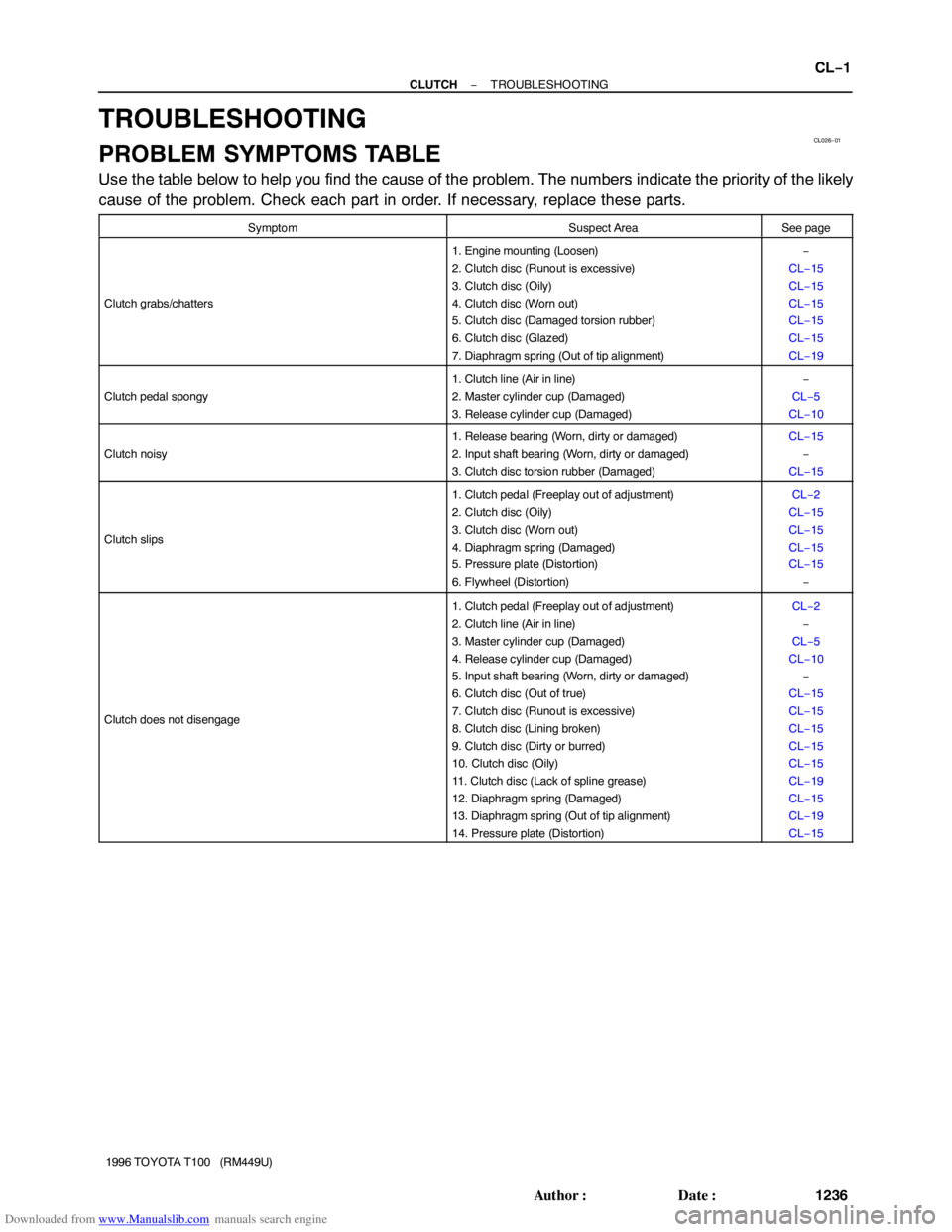
Downloaded from www.Manualslib.com manuals search engine CL026−01
− CLUTCHTROUBLESHOOTING
CL−1
1236 Author�: Date�:
1996 TOYOTA T100 (RM449U)
TROUBLESHOOTING
PROBLEM SYMPTOMS TABLE
Use the table below to help you find the cause of the problem. The numbers indicate the priority of the likely
cause of the problem. Check each part in order. If necessary, replace these parts.
SymptomSuspect AreaSee page
Clutch grabs/chatters
1. Engine mounting (Loosen)
2. Clutch disc (Runout is excessive)
3. Clutch disc (Oily)
4. Clutch disc (Worn out)
5. Clutch disc (Damaged torsion rubber)
6. Clutch disc (Glazed)
7. Diaphragm spring (Out of tip alignment)−
CL−15
CL−15
CL−15
CL−15
CL−15
CL−19
Clutch pedal spongy
1. Clutch line (Air in line)
2. Master cylinder cup (Damaged)
3. Release cylinder cup (Damaged)−
CL−5
CL−10
Clutch noisy
1. Release bearing (Worn, dirty or damaged)
2. Input shaft bearing (Worn, dirty or damaged)
3. Clutch disc torsion rubber (Damaged)CL−15
−
CL−15
Clutch slips
1. Clutch pedal (Freeplay out of adjustment)
2. Clutch disc (Oily)
3. Clutch disc (Worn out)
4. Diaphragm spring (Damaged)
5. Pressure plate (Distortion)
6. Flywheel (Distortion)CL−2
CL−15
CL−15
CL−15
CL−15
−
Clutch does not disengage
1. Clutch pedal (Freeplay out of adjustment)
2. Clutch line (Air in line)
3. Master cylinder cup (Damaged)
4. Release cylinder cup (Damaged)
5. Input shaft bearing (Worn, dirty or damaged)
6. Clutch disc (Out of true)
7. Clutch disc (Runout is excessive)
8. Clutch disc (Lining broken)
9. Clutch disc (Dirty or burred)
10. Clutch disc (Oily)
11. Clutch disc (Lack of spline grease)
12. Diaphragm spring (Damaged)
13. Diaphragm spring (Out of tip alignment)
14. Pressure plate (Distortion)CL−2
−
CL−5
CL−10
−
CL−15
CL−15
CL−15
CL−15
CL−15
CL−19
CL−15
CL−19
CL−15
Page 1282 of 2062

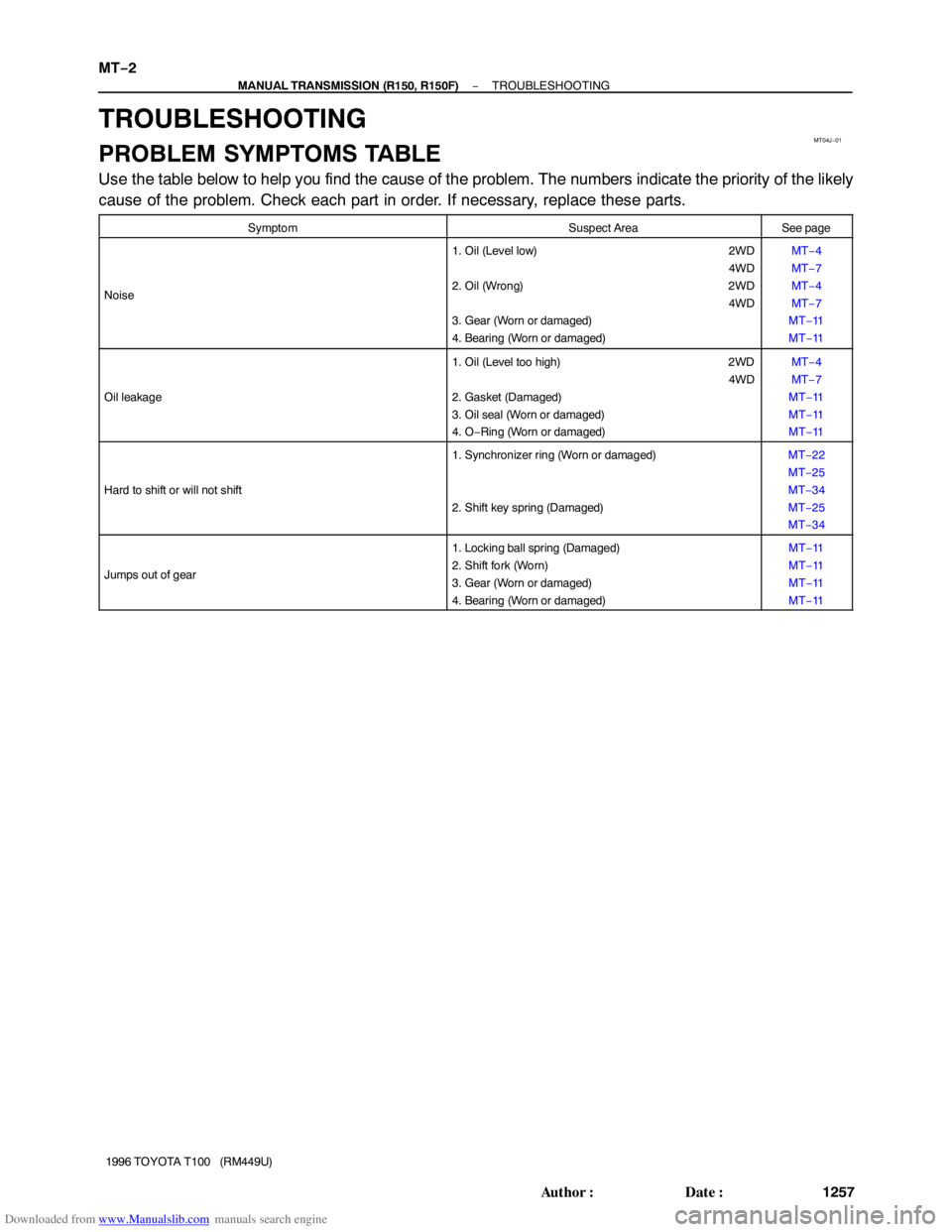
Downloaded from www.Manualslib.com manuals search engine MT04J−01
MT−2
− MANUAL TRANSMISSION (R150, R150F)TROUBLESHOOTING
1257 Author�: Date�:
1996 TOYOTA T100 (RM449U)
TROUBLESHOOTING
PROBLEM SYMPTOMS TABLE
Use the table below to help you find the cause of the problem. The numbers indicate the priority of the likely
cause of the problem. Check each part in order. If necessary, replace these parts.
SymptomSuspect AreaSee page
Noise
1. Oil (Level low) 2WD
4WD
2. Oil (Wrong) 2WD
4WD
3. Gear (Worn or damaged)
4. Bearing (Worn or damaged)MT−4
MT−7
MT−4
MT−7
MT−11
MT−11
Oil leakage
1. Oil (Level too high) 2WD
4WD
2. Gasket (Damaged)
3. Oil seal (Worn or damaged)
4. O−Ring (Worn or damaged)MT−4
MT−7
MT−11
MT−11
MT−11
Hard to shift or will not shift
1. Synchronizer ring (Worn or damaged)
2. Shift key spring (Damaged)MT−22
MT−25
MT−34
MT−25
MT−34
Jumps out of gear
1. Locking ball spring (Damaged)
2. Shift fork (Worn)
3. Gear (Worn or damaged)
4. Bearing (Worn or damaged)MT−11
MT−11
MT−11
MT−11
Page 1323 of 2062

Downloaded from www.Manualslib.com manuals search engine MT057−01
Q04410
Z03582
Q07365
SST
− MANUAL TRANSMISSION (R150, R150F)EXTENSION HOUSING AND TRANSFER ADAPTOR
MT−43
1996 TOYOTA T100 (RM449U)
REPLACEMENT
1. IF NECESSARY, REPLACE REVERSE RESTRICT PIN
(a) Remove the reverse restrict pin.
(1) Using a torx socket wrench (T40), remove the screw
plug.
(2) Using a pin punch and hammer, drive out the slotted
spring pin.
(3) Remove the reverse restrict pin.
(b) Inspect the reverse restrict pin.
Turn and push the reverse restrict pin by hand.
Check for smooth operation.
(c) Install the reverse restrict pin.
(1) Install the reverse restrict pin to the extension hous-
ing or transfer adaptor.
(2) Using a pin punch and hammer, drive in the slotted
spring pin, as shown.
(3) Apply sealant to the plug threads.
Sealant:
Part No. 08833 − 00080, THREE BOND 1344, LOCTITE
242 or equivalent
(4) Using a torx socket wrench (T40), install and torque
the screw plug.
Torque: 19 N·m (190 kgf·cm, 14 ft·lbf)
2. 2WD:
IF NECESSARY, REPLACE EXTENSION HOUSING
OIL SEAL
(a) Remove the dust deflector.
(b) Using a screwdriver, pry out the oil seal.
(c) Using SST and a hammer, drive in a new oil seal.
SST 09950−60010 (09951−00570), 09950−70010
(09951−07150)
Drive in depth: 0 ± 0.5 mm (0 ± 0.020 in.)
(d) Install the deflector.
Page 1327 of 2062
Downloaded from www.Manualslib.com manuals search engine MT03I−01
MT−2
− MANUAL TRANSMISSION (W59)TROUBLESHOOTING
1301 Author�: Date�:
1996 TOYOTA T100 (RM449U)
TROUBLESHOOTING
PROBLEM SYMPTOMS TABLE
Use the table below to help you find the cause of the problem. The numbers indicate the priority of the likely
cause of the problem. Check each part in order. If necessary, replace these parts.
SymptomSuspect AreaSee page
Noise
1. Oil (Level low)
2. Oil (Wrong)
3. Gear (Worn or damaged)
4. Bearing (Worn or damaged)MT−4
MT−4
MT−6
MT−6
Oil leakage
1. Oil (Level too high)
2. Gasket (Damaged)
3. Oil seal (Worn or damaged)
4. O−Ring (Worn or damaged)MT−4
MT−6
MT−6
MT−6
Hard to shift or will not shift
1. Synchronizer ring (Worn or damaged)
2. Shift key spring (Damaged)MT−18
MT−21
MT−30
MT−18
MT−21
MT−30
Jumps out of gear
1. Locking ball spring (Damaged)
2. Shift fork (Worn)
3. Gear (Worn or damaged)
4. Bearing (Worn or damaged)MT−6
MT−6
MT−6
MT−6