Page 957 of 1354

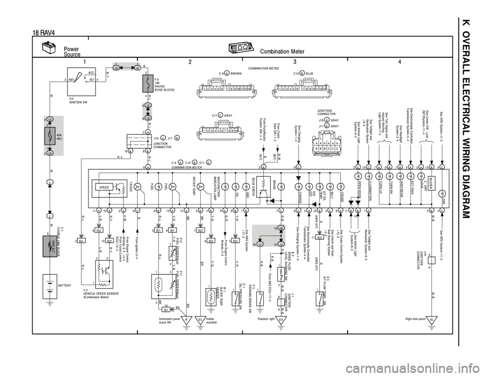
K OVERALL ELECTRICAL WIRING DIAGRAM
1
234
18 RAV4
Power
SourceCombination Meter2ACC
IG 1 AM1 4
2
1
2 1D 91E 8
21B 8
1K 47
1D1
1F
8A
11A 10A 2A 6C 6B 13A 12A 5B 9A 8B 7B
2IG19IG2
10 IG25 ID1 9 ID1 7 IG2
6 IG2 5 IG2B 4
100A ALT
3
F 8
10A
GAUGE
[FUSE BLOCK]
F 7
FUSIBLE LINK BLOCKW 1
WATER TEMP.
SEND ER
From Engine Control
Module< 2-2 < 4-4
From C ruise C ontrol
ECU< 13-4From Engine Contro
Module< 2-3 See ABS System
<17-3See SRS System< 11-2
SPEED
TACHOFU EL FU EL WATER TEMP. MALFUNCTION
INDICATO R LAM POIL ABS
4 B
R- L
WWWR-LL- B R- Y V-WR-L Y-RBR
BR Y- G G-RY-R
R- L R-L R- L
I1 0
IG NIT IO N S W
, C1 1 C
2
111
IF EC ID110
Intake
manifold Instrument panel
brace RH V 2
VEHICLE SPEED SENSOR
(
C o mbina tion M et er)COM B INA T IO N M ET E R C 9 A , J 1 1 B
F11
FUEL SENDER(
Main) F12
FUEL SENDER(
Sub) B 2
BRAKE FLUID
LEVEL WARNING SW
3
2 1
3
R-L L- B R- YR- L Y-R Y-B
BRBR BR Y-GY-R
BATTER Y
BR9C 2C 3C7A 9B 1B 4A 3A 13B
7C 8C 5A 10B 11B B C2B
17 IG2 1B 19
S ee Charging
System< 1-4
BR AKE BU ZZER
S ee E lectronically C ontrolled
Transmission S ystem< 4- 4S e e C ente r D iff. L o ck
(
M/T)
System< 11-4
S ee Headlight
System< 3-4
See Turn Signal and
Hazard Warning
Light System< 7-2 See SRS System< 11-2
S ee Interior Light
System< 6-2
S ee C harging S ys tem< 1- 4 S ee Ele ctr on ic ally C o ntr olled
T ransmission System< 4-4S ee Inte rior Lig ht
System<6-2
R- B W-B
R
(
4W D A /T)
1I 1J
O 1
OIL PRESSURE SW
1
EAIG R adiator rightRight kick panel
P 2
PARKING BRAKE SW1
A 5
A/T FLU ID TEM P. SW
1 2
R-BW-B RW-B
(
4WD A/T)
R-B
2124
1 40A
AM 1
6
B
F ro m Ig nite r< 5- 4
B-Y
10 13 9 8 7 6 5 4 3 2 1101112 139 8 7 6 5 4 3 2 1101112
10 9 8 7 6 5 4 3 2 1B C10 BLUE A C 9 BROWN
C C11 GRAYCO M BINATION M ETER
W-B
CA
BB BBJ10 A
JUNCTION
CONNECTOR
3B
BU LB C HEC K From C lutch
Start SW< 1-2B-W
A AA
A
J 1
JU NC TIO N
CONNECTOR J10
JUNCTION
CONNECTOR
From ABS ECU< 17-4 R-B
C 5S ee U nlock and S eat
B elt W arning S ystem
<3-2
C
ASee Taillight and
Illu min ation Sy ste m
<8-3S ee Ta illig h t a n d
Illumination System< 8- 3
10
1 A
S ee C ruise Control S ystem
<13-36 , C10 B
TUR N LH TUR N RH
HIGH BEAM
ECT PW R C. D IFF
LO C KSRS
ILLUMINATION
OPEN DOOR
CHARGE O/D
OFF A/T OIL
TEM P. BELT CRUISE
AAAAAA
BBBCCCA J10 G R A Y
J11 B G R A Y JUNCTION
CONNECTOR
(M /T )
(
A/T) B
From P a rk/N eu tra l
Position SW <1-315
Page 1132 of 1354
SA0TF−06
W04172
2WD M/T
Snap RingCenter Bearing Bracket
RH Drive Shaft
Snap RingABS Speed Sensor
Tie Rod End
Cotter Pin
Lock Cap LH Drive Shaft
Boot Clamp
Engine
Under
Cover
3 Door vehicle
64 (650, 47)
5 Door vehicle,
All over fender
vehicle
113 (1,150, 83)
�
�
32 (330, 24)
64 (650, 47)
8 (80, 69 in.·lbf)
49 (500, 36)
216 (2,200, 159)
127 (1,300, 94)
Lower Suspension Arm X6
X7
Center Drive Shaft Inner Race Ball Cage Stabilizer Bar Link
Snap Ring
Snap Ring
Dust Cover
Center Bearing Dust Cover
Inboard Joint Tulip Outboard Joint
Shaft No.2 Dust
DeflectorBoot�
�
�
�
�
� �
�N·m (kgf·cm, ft·lbf)
: Specified torque
Non−reusable part
LH SA−18
− SUSPENSION AND AXLEFRONT DRIVE SHAFT
1996 RAV4 (RM447U)
FRONT DRIVE SHAFT
COMPONENTS
Page 1134 of 1354

SA1YB−02
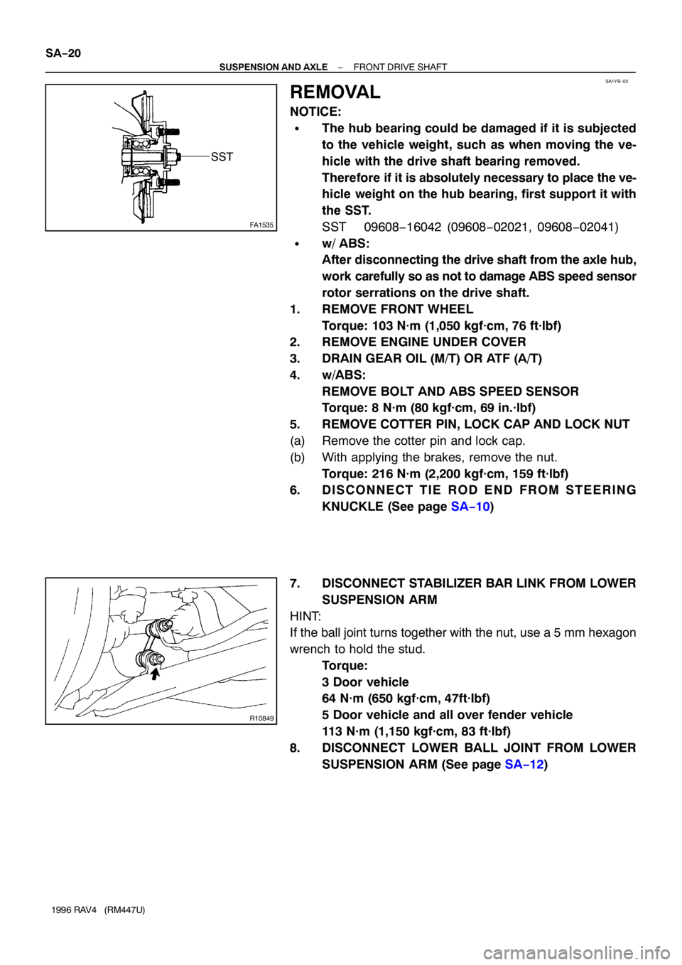
FA1535
SST
R10849
SA−20
− SUSPENSION AND AXLEFRONT DRIVE SHAFT
1996 RAV4 (RM447U)
REMOVAL
NOTICE:
�The hub bearing could be damaged if it is subjected
to the vehicle weight, such as when moving the ve-
hicle with the drive shaft bearing removed.
Therefore if it is absolutely necessary to place the ve-
hicle weight on the hub bearing, first support it with
the SST.
SST 09608−16042 (09608−02021, 09608−02041)
�w/ ABS:
After disconnecting the drive shaft from the axle hub,
work carefully so as not to damage ABS speed sensor
rotor serrations on the drive shaft.
1. REMOVE FRONT WHEEL
Torque: 103 N·m (1,050 kgf·cm, 76 ft·lbf)
2. REMOVE ENGINE UNDER COVER
3. DRAIN GEAR OIL (M/T) OR ATF (A/T)
4. w/ABS:
REMOVE BOLT AND ABS SPEED SENSOR
Torque: 8 N·m (80 kgf·cm, 69 in.·lbf)
5. REMOVE COTTER PIN, LOCK CAP AND LOCK NUT
(a) Remove the cotter pin and lock cap.
(b) With applying the brakes, remove the nut.
Torque: 216 N·m (2,200 kgf·cm, 159 ft·lbf)
6. D I S C O N N E C T T I E R O D E N D F R O M S T E E R I N G
KNUCKLE (See page SA−10)
7. DISCONNECT STABILIZER BAR LINK FROM LOWER
SUSPENSION ARM
HINT:
If the ball joint turns together with the nut, use a 5 mm hexagon
wrench to hold the stud.
Torque:
3 Door vehicle
64 N·m (650 kgf·cm, 47ft·lbf)
5 Door vehicle and all over fender vehicle
113 N·m (1,150 kgf·cm, 83 ft·lbf)
8. DISCONNECT LOWER BALL JOINT FROM LOWER
SUSPENSION ARM (See page SA−12)