Page 1276 of 1354

SR0FD−01
SR−2
− STEERINGTROUBLESHOOTING
1996 RAV4 (RM447U)
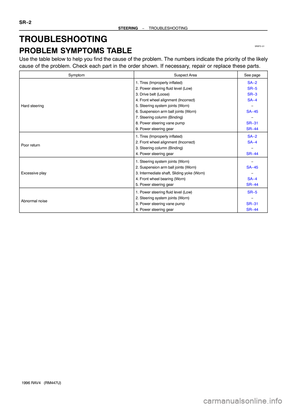
TROUBLESHOOTING
PROBLEM SYMPTOMS TABLE
Use the table below to help you find the cause of the problem. The numbers indicate the priority of the likely
cause of the problem. Check each part in the order shown. If necessary, repair or replace these parts.
SymptomSuspect AreaSee page
Hard steering
1. Tires (Improperly inflated)
2. Power steering fluid level (Low)
3. Drive belt (Loose)
4. Front wheel alignment (Incorrect)
5. Steering system joints (Worn)
6. Suspension arm ball joints (Worn)
7. Steering column (Binding)
8. Power steering vane pump
9. Power steering gearSA−2
SR−5
SR−3
SA−4
−
SA−45
−
SR−31
SR−44
Poor return
1. Tires (Improperly inflated)
2. Front wheel alignment (Incorrect)
3. Steering column (Binding)
4. Power steering gearSA−2
SA−4
−
SR−44
Excessive play
1. Steering system joints (Worn)
2. Suspension arm ball joints (Worn)
3. Intermediate shaft, Sliding yoke (Worn)
4. Front wheel bearing (Worn)
5. Power steering gear−
SA−45
−
SA−4
SR−44
Abnormal noise
1. Power steering fluid level (Low)
2. Steering system joints (Worn)
3. Power steering vane pump
4. Power steering gearSR−5
−
SR−31
SR−44
Page 1277 of 1354

P06717
SR0FH−01
Z00038
DENSO Borroughs
P06723
CORRECT WRONG WRONG
− STEERINGDRIVE BELT
SR−3
1996 RAV4 (RM447U)
DRIVE BELT
INSPECTION
INSPECT DRIVE BELT
(a) Visually check the belt for excessive wear, frayed cords
etc.
If any defect has been found, replace the drive belt.
HINT:
Cracks on the rib side of a belt are considered acceptable. If the
belt has chunks missing from the ribs, it should be replaced.
(b) Using a belt tension gauge, measure the belt tension.
Belt tension gauge:
DENSO BTG−20 (95506−00020)
Borroughs No. BT−33−73F
Drive belt tension:
New belt: 95 − 145 lbf
Used belt: 60 − 100 lbf
If the belt tension is not as specified, adjust it.
HINT:
�”New belt” refers to a belt which has been used less than
5 minutes on a running engine.
�”Used belt” refers to a belt which has been used on a run-
ning engine for 5 minutes or more.
�After installing a belt, check that it fits properly in the
ribbed grooves.
�Check with your hand to confirm that the belt has not
slipped out of the groove on the bottom of the pulley.
�After installing a new belt, run the engine for about 5 min-
utes and recheck the belt tension.
Page 1305 of 1354
SR0FV−02
Z19806
Union Bolt
PS Gear Assembly
Tube ClampPressure Feed Tube
Return Hose
Vacuum Hose
13 (130, 9)
44 (450, 32)
*36 (365, 26)
52 (525, 38)
29 (300, 22)
3 Door vehicle 64 (650, 47)
5 Door vehicle 113 (1,150, 83)
43 (440, 32)
113 (1, 150, 83)
x7
x6
13 (130, 9)
� Gasket
N·m (kgf·cm, ft·lbf)Bracket
BushingDrive Belt
PS Vane Pump Assembly
with Pump Bracket
62 (630, 46)
29 (300, 22)
BushingBracket
� Gasket
Clamp
(A/T)
Front Exhaust Pipe
� Gasket Stabilizer Bar
with Link
Front Suspension
Crossmember Assembly
137 (1, 400, 101)
206 (2, 100, 152)
127 (1, 300, 94)
Engine Under
Cover
127 (1, 300, 94)
137 (1, 400, 101)
112 (1, 140, 82)
8.3 (84, 73 in.·lbf)
48 (490, 35)
�
206 (2, 100, 152)
: Specified torque
* For use with SST � Non−reusable part
W02019
3 Door vehicle 64 (650, 47)
5 Door vehicle 113 (1,150, 83)
− STEERINGPOWER STEERING VANE PUMP
SR−31
1996 RAV4 (RM447U)
POWER STEERING VANE PUMP
COMPONENTS
Page 1307 of 1354
SR0FW−02
R10965
Z13365
Pressure
Feed Tube
SST
R10984
R10966
− STEERINGPOWER STEERING VANE PUMP
SR−33
1996 RAV4 (RM447U)
REMOVAL
1. REMOVE RH AND LH ENGINE UNDER COVERS
Remove the 13 bolts.
2. REMOVE FRONT EXHAUST PIPE
Remove the 2 bolts, 3 nuts and 2 gaskets.
3. REMOVE STABILIZER BAR WITH LINK
(See page SA−48)
4. DISCONNECT RH AND LH LOWER SUSPENSION
ARMS (See page SA−40)
5. REMOVE 2 PS GEAR ASSEMBLY SET BOLTS AND
NUTS
6. REMOVE FRONT SUSPENSION CROSSMEMBER AS-
SEMBLY (See page SA−40)
7. DISCONNECT 2 TUBE CLAMPS
Remove the bolt.
8. DISCONNECT 2 VACUUM HOSES
9. DISCONNECT RETURN HOSE
NOTICE:
Take care not to spill fluid on the drive belt.
10. REMOVE DRIVE BELT
Loosen the 2 bolts.
11. DISCONNECT PRESSURE FEED TUBE
Using SST, disconnect the tube.
SST 09631−22020
12. REMOVE PS VANE PUMP ASSEMBLY WITH PUMP
BRACKET
Remove the 3 bolts.
13. REMOVE PRESSURE FEED TUBE
Remove the union bolt, gasket and tube from the PS vane
pump assembly.
Page 1316 of 1354

SR0G0−03
W01943
Stopper
Pressure Feed
Tube
R10966
W01119
SST
Fulcrum Length
R10981
SR−42
− STEERINGPOWER STEERING VANE PUMP
1996 RAV4 (RM447U)
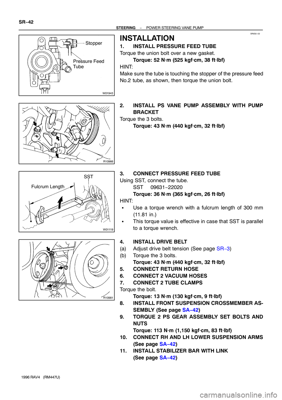
INSTALLATION
1. INSTALL PRESSURE FEED TUBE
Torque the union bolt over a new gasket.
Torque: 52 N·m (525 kgf·cm, 38 ft·lbf)
HINT:
Make sure the tube is touching the stopper of the pressure feed
No.2 tube, as shown, then torque the union bolt.
2. INSTALL PS VANE PUMP ASSEMBLY WITH PUMP
BRACKET
Torque the 3 bolts.
Torque: 43 N·m (440 kgf·cm, 32 ft·lbf)
3. CONNECT PRESSURE FEED TUBE
Using SST, connect the tube.
SST 09631−22020
Torque: 36 N·m (365 kgf·cm, 26 ft·lbf)
HINT:
�Use a torque wrench with a fulcrum length of 300 mm
(11.81 in.)
�This torque value is effective in case that SST is parallel
to a torque wrench.
4. INSTALL DRIVE BELT
(a) Adjust drive belt tension (See page SR−3)
(b) Torque the 3 bolts.
Torque: 43 N·m (440 kgf·cm, 32 ft·lbf)
5. CONNECT RETURN HOSE
6. CONNECT 2 VACUUM HOSES
7. CONNECT 2 TUBE CLAMPS
Torque the bolt.
Torque: 13 N·m (130 kgf·cm, 9 ft·lbf)
8. INSTALL FRONT SUSPENSION CROSSMEMBER AS-
SEMBLY (See page SA−42)
9. TORQUE 2 PS GEAR ASSEMBLY SET BOLTS AND
NUTS
Torque: 113 N·m (1,150 kgf·cm, 83 ft·lbf)
10. CONNECT RH AND LH LOWER SUSPENSION ARMS
(See page SA−42)
11. INSTALL STABILIZER BAR WITH LINK
(See page SA−42)