Page 691 of 1354

S01626
Disconnect
P15391
S01284
SST
S01629
SSTSST
− ENGINE MECHANICALTIMING BELT
EM−25
1996 RAV4 (RM447U)
�Remove the backing paper from a new gasket and
install the gasket evenly to the part of the timing belt
cover shaded black in the illustration.
�After installing the gasket, press down on it so that
the adhesive firmly sticks to the timing belt cover.
(b) Disconnect the engine wire protector between the cylin-
der head cover and No. 3 timing belt cover.
(c) Install the No. 2 timing belt cover with the 4 bolts.
(d) Install the engine wire to the No. 2 timing belt cover.
(e) Install the engine wire protector to the 2 mounting bolts of
the No. 2 timing belt cover in the sequence shown.
15. REMOVE CRANKSHAFT PULLEY
16. INSTALL RH ENGINE MOUNTING BRACKET
Using SST, install the mounting bracket with the 3 bolts.
SST 09249−63010
Torque:
52 N·m (530 kgf·cm, 38 ft·lbf)
35 N·m (360 kgf·cm, 26 ft·lbf) for SST
HINT:
Use a torque wrench with a fulcrum length of 340 mm (13.39 in)
17. INSTALL CRANKSHAFT PULLEY
(a) Align the pulley set key with the key groove of the pulley,
and slide on the pulley.
(b) Using SST (and bolt), install the pulley bolt.
SST 09213−54015 (91651−60855 for type A),
09330−00021
Bolt: Part No. 91121−40665 for type B
Torque: 108 N·m (1,100 kgf·cm, 80 ft·lbf)
18. INSTALL SPARK PLUGS
Page 692 of 1354
S01352
Ground Strap EM−26
− ENGINE MECHANICALTIMING BELT
1996 RAV4 (RM447U)
19. INSTALL RH ENGINE MOUNTING INSULATOR
(a) Attach the mounting insulator to the body and mounting
bracket with the 4 bolts and 2 nuts.
(b) Tighten the 3 bolts holding the mounting insulator to the
body.
Torque: 64 N·m (650 kgf·cm, 47 ft·lbf)
(c) Tighten the 2 nuts and bolt holding the mounting insulator
to the mounting bracket.
Torque:
37 N·m (380 kgf·cm, 27 ft·lbf) for bolt
52 N·m (530 kgf·cm, 38 ft·lbf) for nut
20. INSTALL AND ADJUST PS PUMP DRIVE BELT
21. INSTALL RH ENGINE UNDER COVER
22. INSTALL RH FRONT WHEEL
23. w/ ABS:
INSTALL NO. 3 ABS ACTUATOR BRACKET (See page
BR−41)
24. INSTALL GENERATOR BRACKET
(a) Install the bracket with the 3 bolts.
Torque: 42 N·m (425 kgf·cm, 31 ft·lbf)
(b) Connect the ground strap connector.
25. INSTALL GENERATOR (See page CH−19)
26. INSTALL WIRE HARNESS BRACKET FOR DLC1
27. INSTALL PS RESERVOIR BRACKET AND RES-
ERVOIR
Page 702 of 1354

S01653
1 2
S01646
S01647
S01645
S01432
EM−36
− ENGINE MECHANICALCYLINDER HEAD
1996 RAV4 (RM447U)
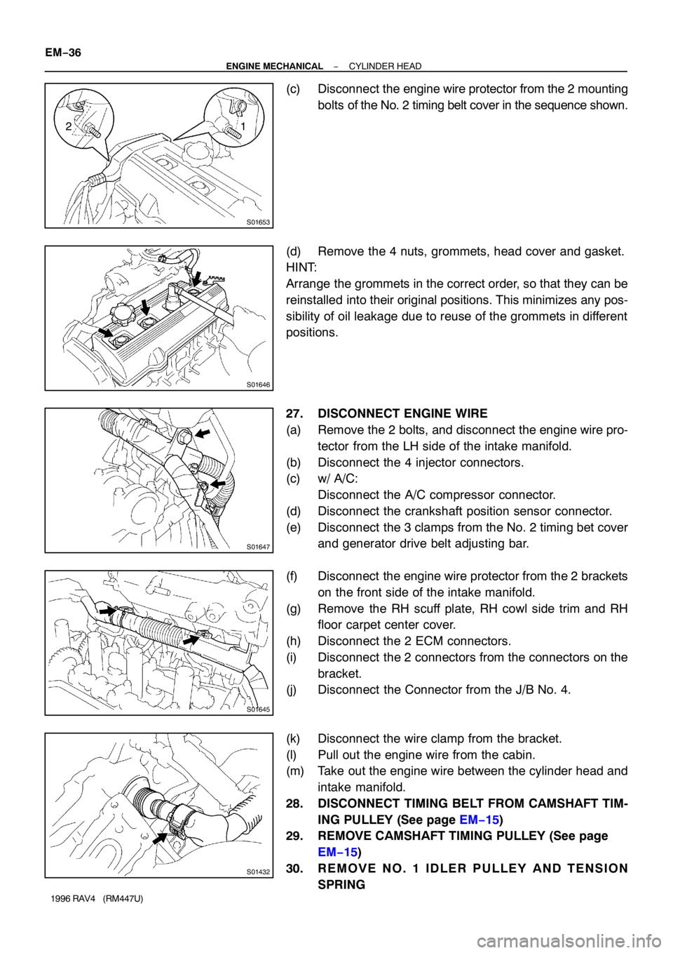
(c) Disconnect the engine wire protector from the 2 mounting
bolts of the No. 2 timing belt cover in the sequence shown.
(d) Remove the 4 nuts, grommets, head cover and gasket.
HINT:
Arrange the grommets in the correct order, so that they can be
reinstalled into their original positions. This minimizes any pos-
sibility of oil leakage due to reuse of the grommets in different
positions.
27. DISCONNECT ENGINE WIRE
(a) Remove the 2 bolts, and disconnect the engine wire pro-
tector from the LH side of the intake manifold.
(b) Disconnect the 4 injector connectors.
(c) w/ A/C:
Disconnect the A/C compressor connector.
(d) Disconnect the crankshaft position sensor connector.
(e) Disconnect the 3 clamps from the No. 2 timing bet cover
and generator drive belt adjusting bar.
(f) Disconnect the engine wire protector from the 2 brackets
on the front side of the intake manifold.
(g) Remove the RH scuff plate, RH cowl side trim and RH
floor carpet center cover.
(h) Disconnect the 2 ECM connectors.
(i) Disconnect the 2 connectors from the connectors on the
bracket.
(j) Disconnect the Connector from the J/B No. 4.
(k) Disconnect the wire clamp from the bracket.
(l) Pull out the engine wire from the cabin.
(m) Take out the engine wire between the cylinder head and
intake manifold.
28. DISCONNECT TIMING BELT FROM CAMSHAFT TIM-
ING PULLEY (See page EM−15)
29. REMOVE CAMSHAFT TIMING PULLEY (See page
EM−15)
30. REMOVE NO. 1 IDLER PULLEY AND TENSION
SPRING
Page 703 of 1354

S01649
S01789
S01794
10 − 45°
Knock
Pin
P03445
Service
BoltDrive Gear
Sub−Gear
− ENGINE MECHANICALCYLINDER HEAD
EM−37
1996 RAV4 (RM447U)
31. REMOVE NO. 3 TIMING BELT COVER
Remove the 3 bolts and timing belt cover.
NOTICE:
�Support the timing belt, so the meshing of the crank-
shaft timing pulley and timing belt does not shift..
�Be careful not to drop anything inside the timing belt
cover
�Do not allow the belt to come into contact with oil, wa-
ter or dust.
32. REMOVE CAMSHAFTS
NOTICE:
Since the thrust clearance of the camshaft is small, the
camshaft must be kept level while it is being removed. If the
camshaft is not kept level, the portion of the cylinder head
receiving the shaft thrust may crack or be damaged, caus-
ing the camshaft to seize or break. To avoid this, the follow-
ing steps should be carried out.
(a) Remove the exhaust camshaft.
(1) Set the knock pin of the intake camshaft at 10 − 45°
BTDC of camshaft angle.
HINT:
The above angle allows No. 2 and No. 4 cylinder cam lobes of
the exhaust camshaft to push their valve lifters evenly.
(2) Secure the exhaust camshaft sub gear to drive gear
with a service bolt.
Recommended service bolt:
Thread diameter6 mm
Thread pitch1.0 mm
Bolt length16 − 20 mm (0.63 − 0.79 in.)
Page 725 of 1354

S01805
S01793
9 10
3 45 6
1 2
7 8
EM7797
Seal Packing
S01649
S01645
− ENGINE MECHANICALCYLINDER HEAD
EM−59
1996 RAV4 (RM447U)
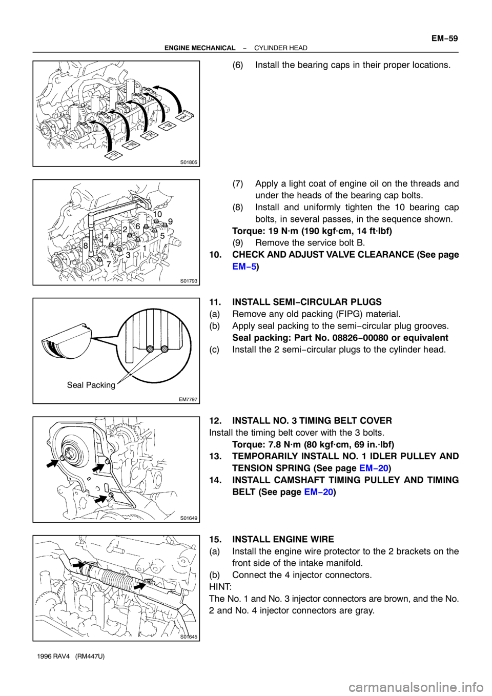
(6) Install the bearing caps in their proper locations.
(7) Apply a light coat of engine oil on the threads and
under the heads of the bearing cap bolts.
(8) Install and uniformly tighten the 10 bearing cap
bolts, in several passes, in the sequence shown.
Torque: 19 N·m (190 kgf·cm, 14 ft·lbf)
(9) Remove the service bolt B.
10. CHECK AND ADJUST VALVE CLEARANCE (See page
EM−5)
11. INSTALL SEMI−CIRCULAR PLUGS
(a) Remove any old packing (FIPG) material.
(b) Apply seal packing to the semi−circular plug grooves.
Seal packing: Part No. 08826−00080 or equivalent
(c) Install the 2 semi−circular plugs to the cylinder head.
12. INSTALL NO. 3 TIMING BELT COVER
Install the timing belt cover with the 3 bolts.
Torque: 7.8 N·m (80 kgf·cm, 69 in.·lbf)
13. TEMPORARILY INSTALL NO. 1 IDLER PULLEY AND
TENSION SPRING (See page EM−20)
14. INSTALL CAMSHAFT TIMING PULLEY AND TIMING
BELT (See page EM−20)
15. INSTALL ENGINE WIRE
(a) Install the engine wire protector to the 2 brackets on the
front side of the intake manifold.
(b) Connect the 4 injector connectors.
HINT:
The No. 1 and No. 3 injector connectors are brown, and the No.
2 and No. 4 injector connectors are gray.
Page 726 of 1354

S01647
S01432
P03283
: Seal Packing
S01658Marking 15°
15°
Z17351
12 EM−60
− ENGINE MECHANICALCYLINDER HEAD
1996 RAV4 (RM447U)
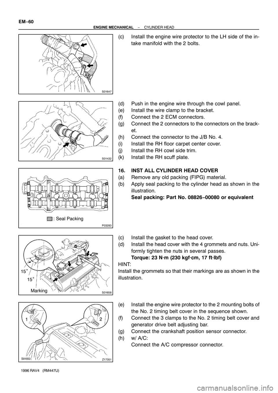
(c) Install the engine wire protector to the LH side of the in-
take manifold with the 2 bolts.
(d) Push in the engine wire through the cowl panel.
(e) Install the wire clamp to the bracket.
(f) Connect the 2 ECM connectors.
(g) Connect the 2 connectors to the connectors on the brack-
et.
(h) Connect the connector to the J/B No. 4.
(i) Install the RH floor carpet center cover.
(j) Install the RH cowl side trim.
(k) Install the RH scuff plate.
16. INST ALL CYLINDER HEAD COVER
(a) Remove any old packing (FIPG) material.
(b) Apply seal packing to the cylinder head as shown in the
illustration.
Seal packing: Part No. 08826−00080 or equivalent
(c) Install the gasket to the head cover.
(d) Install the head cover with the 4 grommets and nuts. Uni-
formly tighten the nuts in several passes.
Torque: 23 N·m (230 kgf·cm, 17 ft·lbf)
HINT:
Install the grommets so that their markings are as shown in the
illustration.
(e) Install the engine wire protector to the 2 mounting bolts of
the No. 2 timing belt cover in the sequence shown.
(f) Connect the 3 clamps to the No. 2 timing belt cover and
generator drive belt adjusting bar.
(g) Connect the crankshaft position sensor connector.
(h) w/ A/C:
Connect the A/C compressor connector.
Page 731 of 1354
EM0EV−02
A04063
N·m (kgf·cm, ft·lbf) : Specified torque
� Non−reusable part
29 (300, 22)
Hold Down ClampHold Down Clamp
BatteryEngine Hood
Battery Tray
Lower Radiator
HosePS Pump
w/ BracketCharcoal Canister
Battery Tray
IAT Sensor ConnectorAir Cleaner Cap
� Gasket
� Gasket
Fuel Inlet Hose
Fuel Filter
Water Inlet
Upper Radiator
Hose
Heater Hose
PS Pump Drive Belt
Generator Drive
Belt
Accelerator Cable
Generator
Generator Drive Belt
Adjusting Bar
Air Filter
EVAP VSV Connector
Air Cleaner Case
Radiator
Reservoir
Relay Block No. 2
Upper Cover
Relay Block No. 2
Wire Harness
A/C Compressor
Type B Type A
Type B Type A
− ENGINE MECHANICALENGINE UNIT
EM−65
1996 RAV4 (RM447U)
ENGINE UNIT
COMPONENTS
Page 737 of 1354
S01434
S01364
S01362
S01363
S01283
B
SST
A
− ENGINE MECHANICALENGINE UNIT
EM−71
1996 RAV4 (RM447U)
29. REMOVE FRONT SUSPENSION CROSSMEMBER
(a) Remove the 2 bolts and 2 nuts holding the PS gear as-
sembly to the front suspension crossmember.
(b) Remove the 2 nuts, and disconnect the engine mounting
center member.
(c) Disconnect the TWC w/ pipe from the ring.
(d) Support the front suspension crossmember with a jack.
(e) Remove the 6 bolts and front suspension crossmember.
30. REMOVE ENGINE MOUNTING CENTER MEMBER
(a) Remove the 2 bolts holding the center member to the
front engine mounting insulator.
(b) Remove the 2 bolts holding the center member to the
body, and remove the center member.
31. DISCONNECT PS PUMP FROM ENGINE
(a) Disconnect the 2 air hoses.
(b) Remove the bolt A.
(c) Using SST and a deep socket wrench, loosen the bolt B.
SST 09249−63010
(d) Remove the drive belt.