Page 1311 of 1354
R10970
W01133
Compressed Air
R10971
A
− STEERINGPOWER STEERING VANE PUMP
SR−37
1996 RAV4 (RM447U)
HINT:
There are 5 vane lengths with the following rotor and cam ring
marks:
Rotor and
cam ring markVane plate
part numberVane plate length mm
(in.)
None44345−1201014.996−14.998
(0.59039−0.59047)
144345−1202014.994−14.996
(0.59032−0.59039)
244345−1203014.992−14.994
(0.59024−0.59032)
344345−1204014.990−14.992
(0.59016−0.59024)
444345−1205014.988−14.990
(0.59008−0.59016)
3. INSPECT FLOW CONTROL VALVE
(a) Coat the flow control valve with power steering fluid and
check that it falls smoothly into the valve hole by its own
weight.
(b) Check the valve for leakage. Close one of the holes and
apply 392−490 kPa (4−5 kgf/cm
2, 57−71 psi) of com-
pressed air into the opposite side, and confirm that air
does not come out from the end hole.
If necessary, replace the valve with one having the same letter
as inscribed on the front housing.
Inscribed mark: A, B, C, D, E or F
Page 1312 of 1354
R08702
Calipers
W01131
Vinyl Tape
W01130
Press
SST
Oil SealSST SR−38
− STEERINGPOWER STEERING VANE PUMP
1996 RAV4 (RM447U)
4. INSPECT SPRING
Using calipers, measure the free length of the spring.
Minimum free length: 36.0 mm (1.42 in.)
If it is not within the specification, replace the spring.
5. IF NECESSARY, REPLACE OIL SEAL
(a) Using a screwdriver with vinyl tape wound around its tip,
remove the oil seal.
NOTICE:
Be careful not to damage the bushing of the front housing.
(b) Coat a new oil seal lip with power steering fluid.
(c) Using SST, press in the oil seal.
SST 09950−60010 (09951−00240),
09950−70010 (09951−07100)
NOTICE:
Make sure to install the oil seal facing the correct direction.
Page 1316 of 1354

SR0G0−03
W01943
Stopper
Pressure Feed
Tube
R10966
W01119
SST
Fulcrum Length
R10981
SR−42
− STEERINGPOWER STEERING VANE PUMP
1996 RAV4 (RM447U)
INSTALLATION
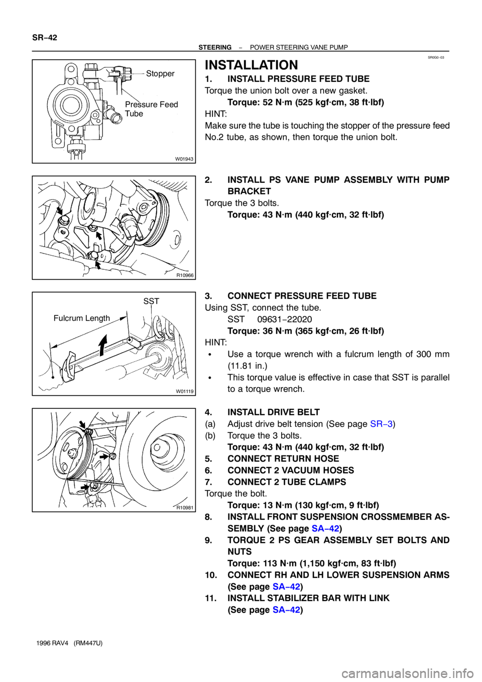
1. INSTALL PRESSURE FEED TUBE
Torque the union bolt over a new gasket.
Torque: 52 N·m (525 kgf·cm, 38 ft·lbf)
HINT:
Make sure the tube is touching the stopper of the pressure feed
No.2 tube, as shown, then torque the union bolt.
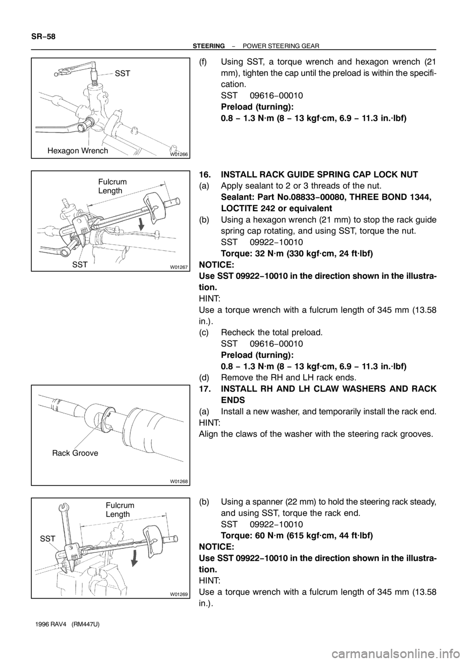
2. INSTALL PS VANE PUMP ASSEMBLY WITH PUMP
BRACKET
Torque the 3 bolts.
Torque: 43 N·m (440 kgf·cm, 32 ft·lbf)
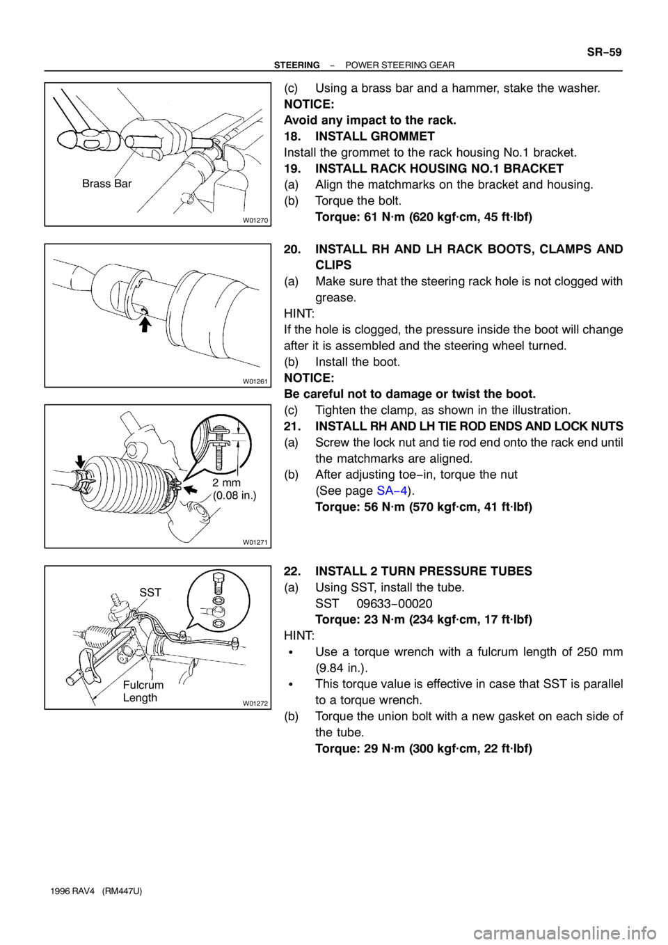
3. CONNECT PRESSURE FEED TUBE
Using SST, connect the tube.
SST 09631−22020
Torque: 36 N·m (365 kgf·cm, 26 ft·lbf)
HINT:
�Use a torque wrench with a fulcrum length of 300 mm
(11.81 in.)
�This torque value is effective in case that SST is parallel
to a torque wrench.
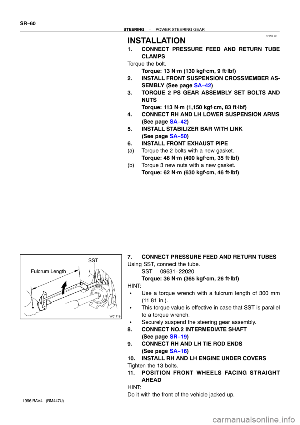
4. INSTALL DRIVE BELT
(a) Adjust drive belt tension (See page SR−3)
(b) Torque the 3 bolts.
Torque: 43 N·m (440 kgf·cm, 32 ft·lbf)
5. CONNECT RETURN HOSE
6. CONNECT 2 VACUUM HOSES
7. CONNECT 2 TUBE CLAMPS
Torque the bolt.
Torque: 13 N·m (130 kgf·cm, 9 ft·lbf)
8. INSTALL FRONT SUSPENSION CROSSMEMBER AS-
SEMBLY (See page SA−42)
9. TORQUE 2 PS GEAR ASSEMBLY SET BOLTS AND
NUTS
Torque: 113 N·m (1,150 kgf·cm, 83 ft·lbf)
10. CONNECT RH AND LH LOWER SUSPENSION ARMS
(See page SA−42)
11. INSTALL STABILIZER BAR WITH LINK
(See page SA−42)
Page 1332 of 1354

W01266
SST
Hexagon Wrench
W01267SSTFulcrum
Length
W01268
Rack Groove
W01269
SSTFulcrum
Length SR−58
− STEERINGPOWER STEERING GEAR
1996 RAV4 (RM447U)
(f) Using SST, a torque wrench and hexagon wrench (21
mm), tighten the cap until the preload is within the specifi-
cation.
SST 09616−00010
Preload (turning):
0.8 − 1.3 N·m (8 − 13 kgf·cm, 6.9 − 11.3 in.·lbf)
16. INSTALL RACK GUIDE SPRING CAP LOCK NUT
(a) Apply sealant to 2 or 3 threads of the nut.
Sealant: Part No.08833−00080, THREE BOND 1344,
LOCTITE 242 or equivalent
(b) Using a hexagon wrench (21 mm) to stop the rack guide
spring cap rotating, and using SST, torque the nut.
SST 09922−10010
Torque: 32 N·m (330 kgf·cm, 24 ft·lbf)
NOTICE:
Use SST 09922−10010 in the direction shown in the illustra-
tion.
HINT:
Use a torque wrench with a fulcrum length of 345 mm (13.58
in.).
(c) Recheck the total preload.
SST 09616−00010
Preload (turning):
0.8 − 1.3 N·m (8 − 13 kgf·cm, 6.9 − 11.3 in.·lbf)
(d) Remove the RH and LH rack ends.
17. INSTALL RH AND LH CLAW WASHERS AND RACK
ENDS
(a) Install a new washer, and temporarily install the rack end.
HINT:
Align the claws of the washer with the steering rack grooves.
(b) Using a spanner (22 mm) to hold the steering rack steady,
and using SST, torque the rack end.
SST 09922−10010
Torque: 60 N·m (615 kgf·cm, 44 ft·lbf)
NOTICE:
Use SST 09922−10010 in the direction shown in the illustra-
tion.
HINT:
Use a torque wrench with a fulcrum length of 345 mm (13.58
in.).
Page 1333 of 1354

W01270
Brass Bar
W01261
W01271
2 mm
(0.08 in.)
W01272
SST
Fulcrum
Length
− STEERINGPOWER STEERING GEAR
SR−59
1996 RAV4 (RM447U)
(c) Using a brass bar and a hammer, stake the washer.
NOTICE:
Avoid any impact to the rack.
18. INSTALL GROMMET
Install the grommet to the rack housing No.1 bracket.
19. INSTALL RACK HOUSING NO.1 BRACKET
(a) Align the matchmarks on the bracket and housing.
(b) Torque the bolt.
Torque: 61 N·m (620 kgf·cm, 45 ft·lbf)
20. INSTALL RH AND LH RACK BOOTS, CLAMPS AND
CLIPS
(a) Make sure that the steering rack hole is not clogged with
grease.
HINT:
If the hole is clogged, the pressure inside the boot will change
after it is assembled and the steering wheel turned.
(b) Install the boot.
NOTICE:
Be careful not to damage or twist the boot.
(c) Tighten the clamp, as shown in the illustration.
21. INSTALL RH AND LH TIE ROD ENDS AND LOCK NUTS
(a) Screw the lock nut and tie rod end onto the rack end until
the matchmarks are aligned.
(b) After adjusting toe−in, torque the nut
(See page SA−4).
Torque: 56 N·m (570 kgf·cm, 41 ft·lbf)
22. INSTALL 2 TURN PRESSURE TUBES
(a) Using SST, install the tube.
SST 09633−00020
Torque: 23 N·m (234 kgf·cm, 17 ft·lbf)
HINT:
�Use a torque wrench with a fulcrum length of 250 mm
(9.84 in.).
�This torque value is effective in case that SST is parallel
to a torque wrench.
(b) Torque the union bolt with a new gasket on each side of
the tube.
Torque: 29 N·m (300 kgf·cm, 22 ft·lbf)
Page 1334 of 1354

SR0G6−02
W01119
SST
Fulcrum Length SR−60
− STEERINGPOWER STEERING GEAR
1996 RAV4 (RM447U)
INSTALLATION
1. CONNECT PRESSURE FEED AND RETURN TUBE
CLAMPS
Torque the bolt.
Torque: 13 N·m (130 kgf·cm, 9 ft·lbf)
2. INSTALL FRONT SUSPENSION CROSSMEMBER AS-
SEMBLY (See page SA−42)
3. TORQUE 2 PS GEAR ASSEMBLY SET BOLTS AND
NUTS
Torque: 113 N·m (1,150 kgf·cm, 83 ft·lbf)
4. CONNECT RH AND LH LOWER SUSPENSION ARMS
(See page SA−42)
5. INSTALL STABILIZER BAR WITH LINK
(See page SA−50)
6. INSTALL FRONT EXHAUST PIPE
(a) Torque the 2 bolts with a new gasket.
Torque: 48 N·m (490 kgf·cm, 35 ft·lbf)
(b) Torque 3 new nuts with a new gasket.
Torque: 62 N·m (630 kgf·cm, 46 ft·lbf)
7. CONNECT PRESSURE FEED AND RETURN TUBES
Using SST, connect the tube.
SST 09631−22020
Torque: 36 N·m (365 kgf·cm, 26 ft·lbf)
HINT:
�Use a torque wrench with a fulcrum length of 300 mm
(11.81 in.).
�This torque value is effective in case that SST is parallel
to a torque wrench.
�Securely suspend the steering gear assembly.
8. CONNECT NO.2 INTERMEDIATE SHAFT
(See page SR−19)
9. CONNECT RH AND LH TIE ROD ENDS
(See page SA−16)
10. INSTALL RH AND LH ENGINE UNDER COVERS
Tighten the 13 bolts.
11. POSITION FRONT WHEELS FACING STRAIGHT
AHEAD
HINT:
Do it with the front of the vehicle jacked up.
Page 1343 of 1354
P10588
Ohmmeter
Continuity
P10589
Ohmmeter
No Continuity
Z10079
Brush Holder Side
Field Frame Side Length
Length ST−8
− STARTINGSTARTER
1996 RAV4 (RM447U)
7. INSPECT FIELD FRAME (FIELD COIL) FOR OPEN
CIRCUIT
Using an ohmmeter, check that there is continuity between the
lead wire and field coil brush lead.
If there is no continuity, replace the field frame.
8. INSPECT FIELD FRAME (FIELD COIL) FOR GROUND
Using an ohmmeter, check that there is no continuity between
the field coil end and field frame.
If there is continuity, repair or replace the field frame.
9. INSPECT BRUSH LENGTH
Using a vernier caliper, measure the brush length.
Standard length: 15.5 mm (0.610 in.)
Minimum length: 10 mm (0.394 in.)
If the length is less than minimum, replace the brush holder and
field frame.