Page 95 of 1354

V08467
18
Noise NOISE PRODUCED WHEN ENGINE STARTS
Whistling noise which becomes high−pitched
when accelerator strongly depressed, disappears
shortly after engine stops.Ye s
Generator noise.
No
Whining noise occurs when A/C is operating.Ye s
A/C noise.
Scratching noise occurs during sudden
acceleration, driving on rough roads or when
ignition switch is turned on.No
Ye s
Fuel gauge noise.
No
Clicking sound heard when horn button is
pressed, then released. Whirring/grating sound
when pushed continuously.Ye s
Horn noise.
No
Murmuring sound stops when engine stops.
NoYe s
Ignition noise.
Tick−tock noise, occurs in co−ordination with
blinking of flasher.Ye s
Turn signal noise.
No
Noise occurs during window washer operation.Ye s
Washer noise.
No
Scratching noise occurs while engine is running,
continues a while even after engine stops.
NoEngine coolant temperature gauge noise. Ye s
Scraping noise in time with wiper beat.
NoYe s
Wiper noise.
Other type of noise.
− BODY ELECTRICALAUDIO SYSTEM
BE−79
1996 RAV4 (RM447U)
Page 215 of 1354

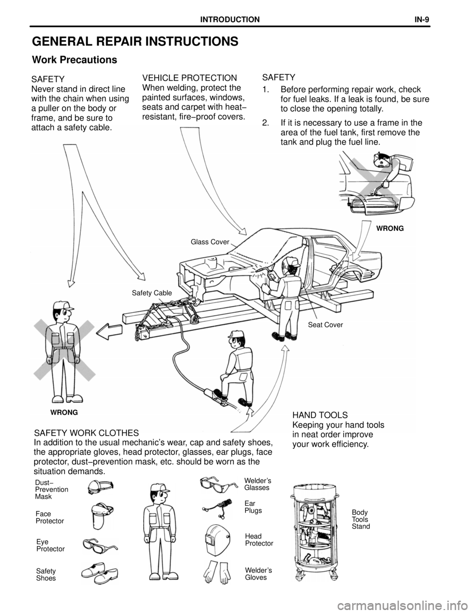
GENERAL REPAIR INSTRUCTIONS
Work Precautions
VEHICLE PROTECTION
When welding, protect the
painted surfaces, windows,
seats and carpet with heat-
resistant, fire-proof covers. SAFETY
Never stand in direct line
with the chain when using
a puller on the body or
frame, and be sure to
attach a safety cable.SAFETY
1. Before performing repair work, check
for fuel leaks. If a leak is found, be sure
to close the opening totally.
2. If it is necessary to use a frame in the
area of the fuel tank, first remove the
tank and plug the fuel line.
WRONG
Glass Cover
Safety Cable
Seat Cover
WRONG
HAND TOOLS
Keeping your hand tools
in neat order improve
your work efficiency. SAFETY WORK CLOTHES
In addition to the usual mechanic's wear, cap and safety shoes,
the appropriate gloves, head protector, glasses, ear plugs, face
protector, dust-prevention mask, etc. should be worn as the
situation demands.
Dust-
Prevention
MaskWelder's
Glasses
Ear
Plugs
Face
ProtectorBody
Tools
Stand
Head
Protector Eye
Protector
Welder's
Gloves Safety
Shoes
INTRODUCTIONINœ9
Page 235 of 1354
BODY PANEL ANTI-RUST AGENT (WAX) APPLICATION AREAS
HINT:
1. Whenever adjusting the doors and hoods, apply anti-rust agent (wax) around the hinges.
2. Even if partially repairing a part, apply anti-rust agent (wax) over the entire application area of the part.
3. Wipe off the anti-rust agent immediately with a rag soaked in a grease, wax and silicone remover, if
accidently applied to other areas.
Fuel Filler Opening Rid Hinge
Hood Hinge
Back Door
Hood
Door Door Hinge
ANTI-RUST TREATMENTARœ9
Page 255 of 1354
INSTALLATION
Assembly MarkAssembly Mark
Fuel Tank Protector Bracket
1. Determine the position of the new parts by the
assembly marks of the inner and outer panels.2. Before welding the new parts, temporarily
install the quarter panel and check the fit.
BODY PANEL REPLACEMENTREœ17
Page 324 of 1354

N09214
DLC 3 DI−4
− DIAGNOSTICSENGINE
1996 RAV4 (RM447U)
�By switching the ECM to check mode when trouble-
shooting, the technician can cause the MIL to light
up for a malfunction that is only detected once or
momentarily (TOYOTA hand−held tester only) (See
page DI−3).
�*2 trip detection logic:
When a logic malfunction is first detected, the mal-
function is temporarily stored in the ECM memory.
If the same malfunction is detected again during the
second drive test, this second detection causes the
MIL to light up.
�The 2 trip repeats the same mode a 2nd time. (How-
ever, the IG switch must be turned OFF between the
1st trip and 2nd trip).
�Freeze frame data:
Freeze frame data records the engine condition
when a misfire (DTC P0300 − P0304) or fuel trim
malfunction (DTC P0171, P0172), or other malfunc-
tion (first malfunction only), is detected.
�Because freeze frame data records the engine
conditions (fuel system, calculator load, engine
coolant temperature, fuel trim, engine speed, ve-
hicle speed, etc.) when the malfunction is detected,
when troubleshooting it is useful for determining
whether the vehicle was running or stopped, the en-
gine warmed up or not, the air−fuel ratio lean or rich,
etc. at the time of the malfunction.
�Priorities for Troubleshooting:
If troubleshooting priorities for multiple diagnostic
codes are given in the applicable diagnostic chart,
these should be followed.
If no instructions are given, troubleshoot DTC according to the
following priorities.
(1) DTC other than fuel trim malfunction (DTC P0171,
P0172), EGR (DTC P0401, P0402), and misfire
(DTC P0300 − P0304).
(2) Fuel trim malfunction (DTC P0171, P0172) and
EGR (DTC P0401, P0402).
(3) Misfire (DTC P0300 − P0304).
(b) Check the DLC3.
The vehicle’s ECM uses V.P.W. (Variable Pulse Width) for
communication to comply with SAE J1850. The terminal
arrangement of DLC3 complies with SAE J1962 and
matches the V.P.W. format.
Page 327 of 1354

− DIAGNOSTICSENGINE
DI−7
1996 RAV4 (RM447U)
(10) After checking the DTC, inspect the applicable cir-
cuit.
(b) Clear the DTC.
The following actions will erase the DTC and freezed
frame data.
(1) Operating the OBDII scan tool (complying with SAE
J1978) or TOYOTA hand−held tester to erase the
codes.
(See the OBDII scan tool’s instruction book for oper-
ating instructions.)
(2) Disconnecting the battery terminals or EFI fuse.
NOTICE:
If the TOYOTA hand−held tester switches the ECM from
normal mode to check mode or vice−versa, or it the ignition
switch is turned from ON to ACC or OFF during check
mode, the DTC and freezed frame data will be erased.
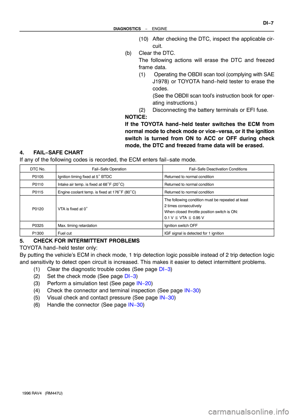
4. FAIL−SAFE CHART
If any of the following codes is recorded, the ECM enters fail−sate mode.
DTC No.Fail−Safe OperationFail−Safe Deactivation Conditions
P0105Ignition timing fixed at 5° BTDCReturned to normal condition
P0110Intake air temp. is fixed at 68°F (20°C)Returned to normal condition
P0115Engine coolant temp. is fixed at 176°F (80°C)Returned to normal condition
P0120VTA is fixed at 0°
The following condition must be repeated at least
2 times consecutively
When closed throttle position switch is ON:
0.1 V � VTA � 0.95 V
P0325Max. timing retardationIgnition switch OFF
P1300Fuel cutIGF signal is detected for 1 ignition
5. CHECK FOR INTERMITTENT PROBLEMS
TOYOTA hand−held tester only:
By putting the vehicle’s ECM in check mode, 1 trip detection logic possible instead of 2 trip detection logic
and sensitivity to detect open circuit is increased. This makes it easier to detect intermittent problems.
(1) Clear the diagnostic trouble codes (See page DI−3)
(2) Set the check mode (See page DI−3)
(3) Perform a simulation test (See page IN−20)
(4) Check the connector and terminal inspection (See page IN−30)
(5) Visual check and contact pressure (See page IN−30)
(6) Handle the connector (See page IN−30)
Page 331 of 1354

S01830
Fuel Inlet Hose
P25066
− DIAGNOSTICSENGINE
DI−11
1996 RAV4 (RM447U)
7 Check fuel pressure.
PREPARATION:
(a) Be sure that enough fuel is in the tank.
(b) Turn ignition switch ON.
(c) Connect the TOYOTA hand−held tester to DLC3 on the
vehicle.
(d) Use ACTIVE TEST mode to operate the fuel pump.
(e) If you have no TOYOTA hand−held tester, connect the
positive (+) and negative (−) leads from the battery to the
fuel pump connector (See page SF−5).
CHECK:
Check for fuel pressure in the inlet hose when it is pinched off.
HINT:
At this time, you will hear a fuel flowing noise.
NG Proceed to page SF−5 and continue to trouble-
shoot.
OK
8 Check for spark.
PREPARATION:
(a) Disconnect the high−tension cord from spark plug.
(b) Remove spark plug.
(c) Install spark plug to high−tension cord.
(d) Disconnect injector connector.
(e) Ground the spark plug.
CHECK:
Check if spark occurs while engine is being cranked.
NOTICE:
To prevent excess fuel being injected from the injectors
during this test, do not crank the engine for more than 5 −
10 seconds at a time.
NG Proceed to page IG−1 and continue to trouble-
shoot.
OK
Proceed to matrix chart of problem systems
on page DI−20.
Page 332 of 1354

DI−12
− DIAGNOSTICSENGINE
1996 RAV4 (RM447U)
7. ENGINE OPERATING CONDITION
NOTICE:
The value given below for ”Normal Condition” are representative values, so a vehicle may still be
normal even it its value varies from those listed here. So do not decide whether a part is faulty or not
solely according to the ”Normal Condition” here.
(a) CARB Mandated Signals
TOYOTA hand−held tester displayMeasurement ItemNormal Condition *
FUEL SYS #1
Fuel System Bank 1
OPEN: Air−fuel ratio feedback stopped
CLOSED: Air−fuel ratio feedback operating
Idling after warning up: CLOSED
CALC LOAD
Calculator Load:
Current intake air volume as a proportion of max.
intake air volumeIdling: 20.7 − 48.4 %
Racing without load (2,500 rpm) : 17.7 − 45.3 %
COOLANT TEMPEngine Coolant Temperature Sensor ValueAfter warning up: 80 − 95°C (176 − 203°F)
SHORT FT #1Short−term Fuel Trim Bank 10 ± 20 %
LONG FT #1Long−term Fuel Trim Bank 10 ± 20 %
ENGINE SPDEngine SpeedIdling: 700 ± 50 rpm
VEHICLE SPDVehicle SpeedVehicle Stopped: 0 km/h (0 mph)
IGN ADVANCEIgnition Advance
Ignition Timing of Cylinder No.1Idling: BTDC 0 − 10°
INTAKE AIRIntake Air Temperature Sensor ValueEquivalent to Ambient Temp.
MAPAbsolute Pressure Inside Intake ManifoldIdling: 21 − 49 kPa
Racing without load (2,500 rpm): 17 − 46 kPa
THROTTLE POS
Voltage Output of Throttle Position Sensor
Calculated as a Percentage
0V → 0 %, 5V → 100 %Throttle Fully Closed: 6 − 16 %
Throttle Fully Open: 64 − 98 %
O2S B1, S1Voltage Output of Oxygen Sensor
Bnak 1,Sensor 1Idling : 0.1 − 0.9 V
O2FT B1, S1Oxygen Sensor Fuel Trim Bank 1, Sensor 1
(Same as SHORT FT #1)0 ± 20 %
O2S B1, S2Voltage Output of Oxygen Sensor
Bank 1, Sensor 2Driving 50 km/h (31 mph): 0.1 − 0.9 V
*: If no conditions are specifically stated for ”Idling”, it means the shift lever is at N or P position, the A/C switch
is OFF and all accessory switches are OFF.