Page 957 of 1354

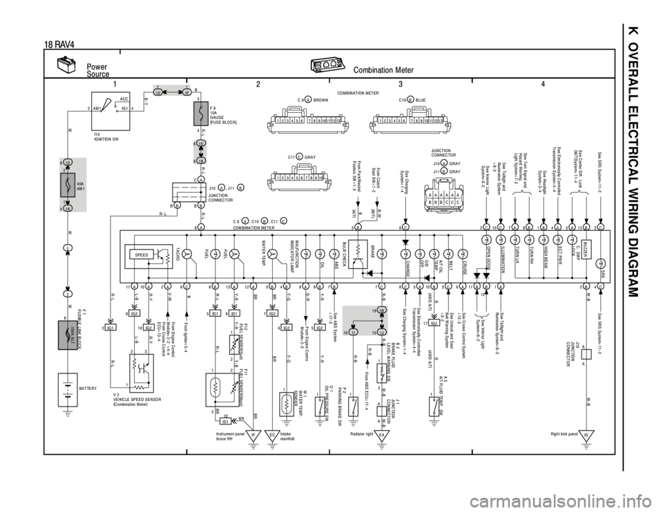
K OVERALL ELECTRICAL WIRING DIAGRAM
1
234
18 RAV4
Power
SourceCombination Meter2ACC
IG 1 AM1 4
2
1
2 1D 91E 8
21B 8
1K 47
1D1
1F
8A
11A 10A 2A 6C 6B 13A 12A 5B 9A 8B 7B
2IG19IG2
10 IG25 ID1 9 ID1 7 IG2
6 IG2 5 IG2B 4
100A ALT
3
F 8
10A
GAUGE
[FUSE BLOCK]
F 7
FUSIBLE LINK BLOCKW 1
WATER TEMP.
SEND ER
From Engine Control
Module< 2-2 < 4-4
From C ruise C ontrol
ECU< 13-4From Engine Contro
Module< 2-3 See ABS System
<17-3See SRS System< 11-2
SPEED
TACHOFU EL FU EL WATER TEMP. MALFUNCTION
INDICATO R LAM POIL ABS
4 B
R- L
WWWR-LL- B R- Y V-WR-L Y-RBR
BR Y- G G-RY-R
R- L R-L R- L
I1 0
IG NIT IO N S W
, C1 1 C
2
111
IF EC ID110
Intake
manifold Instrument panel
brace RH V 2
VEHICLE SPEED SENSOR
(
C o mbina tion M et er)COM B INA T IO N M ET E R C 9 A , J 1 1 B
F11
FUEL SENDER(
Main) F12
FUEL SENDER(
Sub) B 2
BRAKE FLUID
LEVEL WARNING SW
3
2 1
3
R-L L- B R- YR- L Y-R Y-B
BRBR BR Y-GY-R
BATTER Y
BR9C 2C 3C7A 9B 1B 4A 3A 13B
7C 8C 5A 10B 11B B C2B
17 IG2 1B 19
S ee Charging
System< 1-4
BR AKE BU ZZER
S ee E lectronically C ontrolled
Transmission S ystem< 4- 4S e e C ente r D iff. L o ck
(
M/T)
System< 11-4
S ee Headlight
System< 3-4
See Turn Signal and
Hazard Warning
Light System< 7-2 See SRS System< 11-2
S ee Interior Light
System< 6-2
S ee C harging S ys tem< 1- 4 S ee Ele ctr on ic ally C o ntr olled
T ransmission System< 4-4S ee Inte rior Lig ht
System<6-2
R- B W-B
R
(
4W D A /T)
1I 1J
O 1
OIL PRESSURE SW
1
EAIG R adiator rightRight kick panel
P 2
PARKING BRAKE SW1
A 5
A/T FLU ID TEM P. SW
1 2
R-BW-B RW-B
(
4WD A/T)
R-B
2124
1 40A
AM 1
6
B
F ro m Ig nite r< 5- 4
B-Y
10 13 9 8 7 6 5 4 3 2 1101112 139 8 7 6 5 4 3 2 1101112
10 9 8 7 6 5 4 3 2 1B C10 BLUE A C 9 BROWN
C C11 GRAYCO M BINATION M ETER
W-B
CA
BB BBJ10 A
JUNCTION
CONNECTOR
3B
BU LB C HEC K From C lutch
Start SW< 1-2B-W
A AA
A
J 1
JU NC TIO N
CONNECTOR J10
JUNCTION
CONNECTOR
From ABS ECU< 17-4 R-B
C 5S ee U nlock and S eat
B elt W arning S ystem
<3-2
C
ASee Taillight and
Illu min ation Sy ste m
<8-3S ee Ta illig h t a n d
Illumination System< 8- 3
10
1 A
S ee C ruise Control S ystem
<13-36 , C10 B
TUR N LH TUR N RH
HIGH BEAM
ECT PW R C. D IFF
LO C KSRS
ILLUMINATION
OPEN DOOR
CHARGE O/D
OFF A/T OIL
TEM P. BELT CRUISE
AAAAAA
BBBCCCA J10 G R A Y
J11 B G R A Y JUNCTION
CONNECTOR
(M /T )
(
A/T) B
From P a rk/N eu tra l
Position SW <1-315
Page 959 of 1354

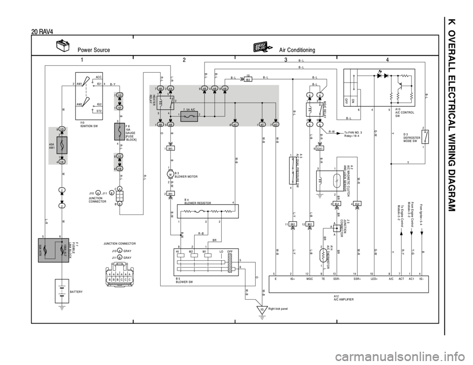
K OVERALL ELECTRICAL WIRING DIAGRAM
1
234
20 RAV4
1 AC C
IG 1
IG 2
ST2 AM1
2
AM2
1D 9
1K 4
21D 7
1E 81F 1
1B 84B 74A2
22 1
M 4B 5 4B 1
2IH1 1IH12 1
5 3 66
66
6 EA1
3 IB210
3IG2
11 IB2 4C 7 4C 1 4C 8 4B 8
4
4 87 10 13 14 9 12 2 5 1 2 8
6
IG 2 3 1
1 2 1
4
5 HI M2 M1 LO64 5
15
6
1 I1 0
IG N ITION S W
F 8
10A
GAUGE
[FU S E
BLOCK]
BBB-WB-WB- W
W W R-L L-R
BR-LR-LR-L O
L-R L- B B-R B-R Y
W-RR-Y Y-GB
Y
G-W
L BR BR W-R
L-B
W-BL-Y
L-B
OW-B W-B
W-B W-B
R-B
BR
W
B-L
R-W B-L
B-L
B 4
BLOWER RESISTOR
Power Source Air Conditioning
R ight kick panel 34 B-Y
7. 5A A/C
B 3
BLOWER MOTORB-L
A 3
A/C DUAL PRESSURE SW
L- Y
F 7
FUSIBLE
LINK BLOCK
BATTERY
50A HTR 100A ALT
B 5
BLO W ER SWA13
A/C CONTROL
SW
2 1
A 2
A/C MAGNETIC CLUTCH
AND LOCK SENSOR
A14
A/C THERMISTOR
IG- E IG+ MGC TE SSR- SSR+ LED+ A/C ACT AC1
A12
A/C AMPLIFIER
To E ngine C ontrol
M odule< 2- 2 F rom Ign iter< 5- 4
B-L MG/C RELAY ON
OFF
HEATER
RELAY
40A
AM1
521
43
2 24
G-W
B- L
To FAN NO. 3
Relay< 19-4 B-L
4IG2
12 IB2
BR F rom E ngine C ontrol
Module<2-2
B-L 4B 94B4
BR
A
A
A
J 3
JUNCTION
CONNECTOR
B- L
B-L
1 2B- L
Y D 3
D EFR OSTER
MODE SW
W-B
CA
BB J10 A , J11 B
JU NC TION
CONNECTOR
AAAAAA
BBBCCC JUNCTION CONNECTOR
B J11 G R A YA J10 G R A Y
OFF
Page 1106 of 1354

RS0QA−02
AB0152
SST
− SUPPLEMENTAL RESTRAINT SYSTEMSTEERING WHEEL PAD AND SPIRAL CABLE
RS−11
1996 RAV4 (RM447U)
DISPOSAL
HINT:
When scrapping vehicle equipped with an SRS or disposing of
a steering wheel pad (with airbag), always first deploy the air-
bag in accordance with the procedure described below. If any
abnormality occurs with the airbag deployment, contact the
SERVICE DEPT. of TOYOTA MOTOR SALES, U.S.A., INC.
When disposing of a steering wheel pad with an airbag
deployed in a collision, follow the same procedure given in step
1−(d) in ”DISPOSAL”.
CAUTION:
�Never dispose of a steering wheel pad which has an
undeployed airbag.
�The airbag produces a sizeable exploding sound
when it deploys, so perform the operation out−of−
doors and where it will not create a nuisance to
nearby residents.
�When deploying the airbag, always use the specified
SST (SRS Airbag Deployment Tool). Perform the op-
eration in a place away from electrical noise.
SST 09082−00700
�When deploying an airbag, perform the operation at
least 10 m (33 ft) away from the steering wheel pad.
�The steering wheel pad is very hot when the airbag is
deployed, so leave it alone for at least 30 minutes af-
ter deployment.
�Use gloves and safety glasses when handling a steer-
ing wheel pad with deployed airbag.
�Always wash your hands with water after completing
the operation.
�Do not apply water, etc. to a steering wheel pad with
deployed airbag.
Page 1215 of 1354

SF0Q4−03
− SFISFI SYSTEM
SF−1
1996 RAV4 (RM447U)
SFI SYSTEM
PRECAUTION
1. BEFORE WORKING ON THE FUEL SYSTEM, DISCON-
NECT THE NEGATIVE (−) TERMINAL CABLE FROM
THE BATTERY
HINT:
Any diagnostic trouble code retained by the computer will be
erased when the negative (−) terminal cable is removed.
Therefore, if necessary, read the diagnosis before removing the
terminal.
2. DO NOT SMOKE OR WORK NEAR AN OPEN FLAME
WHEN WORKING ON THE FUEL SYSTEM
3. KEEP GASOLINE AWAY FROM RUBBER OR LEATH-
ER PARTS
4. MAINTENANCE PRECAUTIONS
(a) In event of engine misfire, these precautions should be
taken.
(1) Check proper connection to battery terminals, etc.
(2) After repair work, check that the ignition coil termi-
nals and all other ignition system lines are recon-
nected securely.
(3) When cleaning the engine compartment, be espe-
cially careful to protect the electrical system from
water.
(b) Precautions when handling oxygen sensor.
(1) Do not allow oxygen sensor to drop or hit against an
object.
(2) Do not allow the sensor to come into contact with
water.
5. IF VEHICLE IS EQUIPPED WITH MOBILE RADIO SYS-
TEM (HAM, CB, ETC.)
If the vehicle is equipped with a mobile communication system,
refer to the precaution in the IN section.
6. AIR INDUCTION SYSTEM
(a) Separation of the engine oil dipstick, oil filler cap, PCV
hose, etc. may cause the engine to run out of tune.
(b) Disconnection, looseness or cracks in the parts of the air
induction system between the throttle body and cylinder
head will allow air suction and cause the engine to run out
of tune.
7. ELECTRONIC CONTROL SYSTEM
(a) Before removing SFI wiring connectors, terminals, etc.,
first disconnect the power by either turning the ignition
switch to LOCK or disconnecting the negative (−) terminal
cable from the battery.
HINT:
Always check the diagnostic trouble code before disconnecting
the negative (−) terminal cable from the battery.