Page 95 of 1354

V08467
18
Noise NOISE PRODUCED WHEN ENGINE STARTS
Whistling noise which becomes high−pitched
when accelerator strongly depressed, disappears
shortly after engine stops.Ye s
Generator noise.
No
Whining noise occurs when A/C is operating.Ye s
A/C noise.
Scratching noise occurs during sudden
acceleration, driving on rough roads or when
ignition switch is turned on.No
Ye s
Fuel gauge noise.
No
Clicking sound heard when horn button is
pressed, then released. Whirring/grating sound
when pushed continuously.Ye s
Horn noise.
No
Murmuring sound stops when engine stops.
NoYe s
Ignition noise.
Tick−tock noise, occurs in co−ordination with
blinking of flasher.Ye s
Turn signal noise.
No
Noise occurs during window washer operation.Ye s
Washer noise.
No
Scratching noise occurs while engine is running,
continues a while even after engine stops.
NoEngine coolant temperature gauge noise. Ye s
Scraping noise in time with wiper beat.
NoYe s
Wiper noise.
Other type of noise.
− BODY ELECTRICALAUDIO SYSTEM
BE−79
1996 RAV4 (RM447U)
Page 298 of 1354
CO0BF−03
S06209
No.3 ABS Actuator Bracket
Engine Wire
Generator
Generator
Drive Belt
PS Pump
Drive BeltGround Strap
Connector
Generator
BracketPS Reservoir Bracket
PS Reservoir
RH Engine Mounting Insulator
RH Engine Mounting Bracket
RH Engine
Under Cover
N·m (kgf·cm, ft·lbf): Specified Torque
37 (380, 27)
52 (530, 38)
52 (530, 38)
52 (530, 38)
52 (530, 38)
52 (530, 38)52 (530, 38)
− COOLINGWATER PUMP
CO−3
1996 RAV4 (RM447U)
WATER PUMP
COMPONENTS
Page 300 of 1354
CO0BG−02
S01613
P15462
P15546
1
3
2
P15463
Disconnect
− COOLINGWATER PUMP
CO−5
1996 RAV4 (RM447U)
REMOVAL
1. REMOVE RH ENGINE UNDER COVER
2. DRAIN ENGINE COOLANT
3. REMOVE TIMING BELT (See page EM−15)
4. DISCONNECT LOWER RADIATOR HOSE FROM
WATER INLET
5. REMOVE TIMING BELT TENSION SPRING AND NO.2
IDLER PULLEY
6. REMOVE GENERATOR DRIVE BELT ADJUSTING
BAR
(a) Disconnect the crankshaft position sensor connector
clamp.
(b) Remove the bolt and adjusting bar.
7. REMOVE WATER PUMP AND WATER PUMP COVER
ASSEMBLY
(a) Remove the 2 nuts holding the water pump to the water
bypass pipe.
(b) Remove the 3 bolts in the sequence shown.
(c) Disconnect the water pump cover from the water bypass
pipe, and remove the water pump and water pump cover
assembly.
(d) Remove the gasket and 2 O−ring from the water pump
and water bypass pipe.
Page 303 of 1354

CO0BI−03
P13480
New O−Ring
New Gasket
P15547
New O−Ring
P15464
Connect
Z16489
3
1
2 CO−8
− COOLINGWATER PUMP
1996 RAV4 (RM447U)
INSTALLATION
1. INSTALL WATER PUMP TO WATER PUMP COVER
Install a new gasket and the water pump with the 3 bolts.
Torque: 8.8 N·m (90 kgf·cm, 78 in.·lbf)
2. INSTALL WATER PUMP AND WATER PUMP COVER
ASSEMBLY
(a) Install new O−ring and gasket to water pump cover.
(b) Install a new O−ring to the water bypass pipe.
(c) Apply soapy water to the O−ring on the water bypass
pipe.
(d) Connect the water pump cover to the water bypass pipe.
Do not install the nuts yet.
(e) Install the water pump with the 3 bolts. Tighten the bolts
in the sequence shown.
Torque: 8.8 N·m (90 kgf·cm, 78 in.·lbf)
(f) Install the 2 nuts holding the water pump cover to the wa-
ter bypass pipe.
Torque: 9.3 N·m (95 kgf·cm, 82 in.·lbf)
3. INSTALL GENERATOR DRIVE BELT ADJUSTING BAR
(a) Install the adjusting bar with the bolt.
Torque: 27 N·m (275 kgf·cm, 20 ft·lbf)
(b) Connect the crankshaft position sensor connector clamp.
4. INSTALL NO.2 IDLER PULLEY AND TIMING BELT
TENSION SPRING
5. CONNECT LOWER RADIATOR HOSE
6. INSTALL TIMING BELT (See page EM−20)
7. FILL WITH ENGINE COOLANT
8. START ENGINE AND CHECK FOR COOLANT LEAKS
9. INSTALL RH ENGINE UNDER COVER
Page 383 of 1354

− DIAGNOSTICSENGINE
DI−63
1996 RAV4 (RM447U)
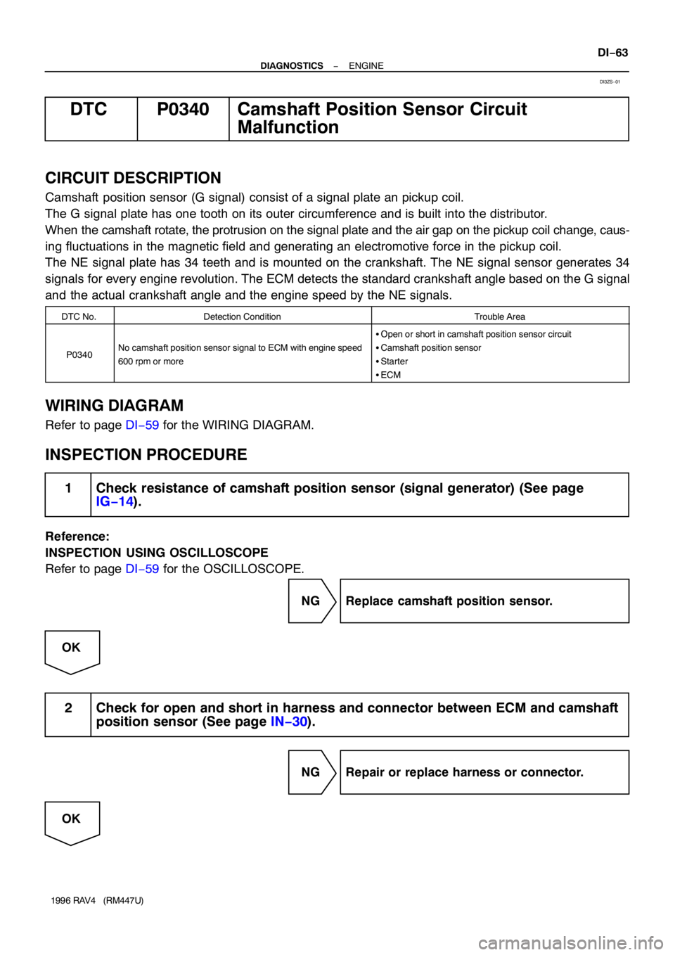
DTC P0340 Camshaft Position Sensor Circuit
Malfunction
CIRCUIT DESCRIPTION
Camshaft position sensor (G signal) consist of a signal plate an pickup coil.
The G signal plate has one tooth on its outer circumference and is built into the distributor.
When the camshaft rotate, the protrusion on the signal plate and the air gap on the pickup coil change, caus-
ing fluctuations in the magnetic field and generating an electromotive force in the pickup coil.
The NE signal plate has 34 teeth and is mounted on the crankshaft. The NE signal sensor generates 34
signals for every engine revolution. The ECM detects the standard crankshaft angle based on the G signal
and the actual crankshaft angle and the engine speed by the NE signals.
DTC No.Detection ConditionTrouble Area
P0340No camshaft position sensor signal to ECM with engine speed
600 rpm or more
�Open or short in camshaft position sensor circuit
�Camshaft position sensor
�Starter
�ECM
WIRING DIAGRAM
Refer to page DI−59 for the WIRING DIAGRAM.
INSPECTION PROCEDURE
1 Check resistance of camshaft position sensor (signal generator) (See page
IG−14).
Reference:
INSPECTION USING OSCILLOSCOPE
Refer to page DI−59 for the OSCILLOSCOPE.
NG Replace camshaft position sensor.
OK
2 Check for open and short in harness and connector between ECM and camshaft
position sensor (See page IN−30).
NG Repair or replace harness or connector.
OK
DI3ZS−01
Page 671 of 1354

EM0EI−02
S01653
21
S01367
− ENGINE MECHANICALVALVE CLEARANCE
EM−5
1996 RAV4 (RM447U)
VALVE CLEARANCE
INSPECTION
HINT:
Inspect and adjust the valve clearance when the engine is cold.
1. DISCONNECT PS RESERVOIR
2. REMOVE CYLINDER HEAD COVER
(a) Disconnect the accelerator cable from the throttle body.
(b) Disconnect the accelerator cable from the clamp on the
intake manifold.
(c) Disconnect the accelerator cable from the clamp on the
generator bracket.
(d) Disconnect the A/T throttle control cable from the throttle
body.
(e) Disconnect the PCV hose from the air cleaner hose.
(f) Disconnect the PCV hose from the intake manifold.
(g) Disconnect the high−tension cords from the spark plugs.
(h) Remove the 2 bolts, and disconnect the accelerator cable
bracket from the intake manifold.
(i) Disconnect the engine wire protector from the 2 mounting
bolts of the No. 2 timing belt cover in the sequence shown.
(j) Remove the 4 nuts, grommets, cylinder head cover and
gasket.
HINT:
Arrange the grommets in the correct order, so that they can be
reinstalled into their original positions. This minimizes any pos-
sibility of oil leakage due to reuse of the grommets in different
positions.
Page 681 of 1354

EM0EM−03
S01283
B
SST
A
S01358
Oil Pump
S01630
SST
SST
− ENGINE MECHANICALTIMING BELT
EM−15
1996 RAV4 (RM447U)
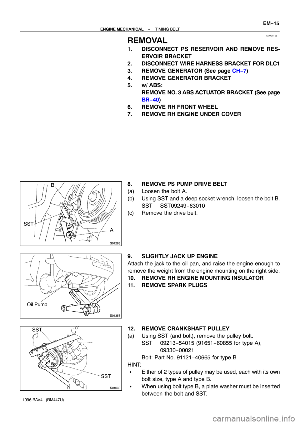
REMOVAL
1. DISCONNECT PS RESERVOIR AND REMOVE RES-
ERVOIR BRACKET
2. DISCONNECT WIRE HARNESS BRACKET FOR DLC1
3. REMOVE GENERATOR (See page CH−7)
4. REMOVE GENERATOR BRACKET
5. w/ ABS:
REMOVE NO. 3 ABS ACTUATOR BRACKET (See page
BR−40)
6. REMOVE RH FRONT WHEEL
7. REMOVE RH ENGINE UNDER COVER
8. REMOVE PS PUMP DRIVE BELT
(a) Loosen the bolt A.
(b) Using SST and a deep socket wrench, loosen the bolt B.
SST SST09249−63010
(c) Remove the drive belt.
9. SLIGHTLY JACK UP ENGINE
Attach the jack to the oil pan, and raise the engine enough to
remove the weight from the engine mounting on the right side.
10. REMOVE RH ENGINE MOUNTING INSULATOR
11. REMOVE SPARK PLUGS
12. REMOVE CRANKSHAFT PULLEY
(a) Using SST (and bolt), remove the pulley bolt.
SST 09213−54015 (91651−60855 for type A),
09330−00021
Bolt: Part No. 91121−40665 for type B
HINT:
�Either of 2 types of pulley may be used, each with its own
bolt size, type A and type B.
�When using bolt type B, a plate washer must be inserted
between the bolt and SST.
Page 692 of 1354
S01352
Ground Strap EM−26
− ENGINE MECHANICALTIMING BELT
1996 RAV4 (RM447U)
19. INSTALL RH ENGINE MOUNTING INSULATOR
(a) Attach the mounting insulator to the body and mounting
bracket with the 4 bolts and 2 nuts.
(b) Tighten the 3 bolts holding the mounting insulator to the
body.
Torque: 64 N·m (650 kgf·cm, 47 ft·lbf)
(c) Tighten the 2 nuts and bolt holding the mounting insulator
to the mounting bracket.
Torque:
37 N·m (380 kgf·cm, 27 ft·lbf) for bolt
52 N·m (530 kgf·cm, 38 ft·lbf) for nut
20. INSTALL AND ADJUST PS PUMP DRIVE BELT
21. INSTALL RH ENGINE UNDER COVER
22. INSTALL RH FRONT WHEEL
23. w/ ABS:
INSTALL NO. 3 ABS ACTUATOR BRACKET (See page
BR−41)
24. INSTALL GENERATOR BRACKET
(a) Install the bracket with the 3 bolts.
Torque: 42 N·m (425 kgf·cm, 31 ft·lbf)
(b) Connect the ground strap connector.
25. INSTALL GENERATOR (See page CH−19)
26. INSTALL WIRE HARNESS BRACKET FOR DLC1
27. INSTALL PS RESERVOIR BRACKET AND RES-
ERVOIR