Page 768 of 1354

P13453
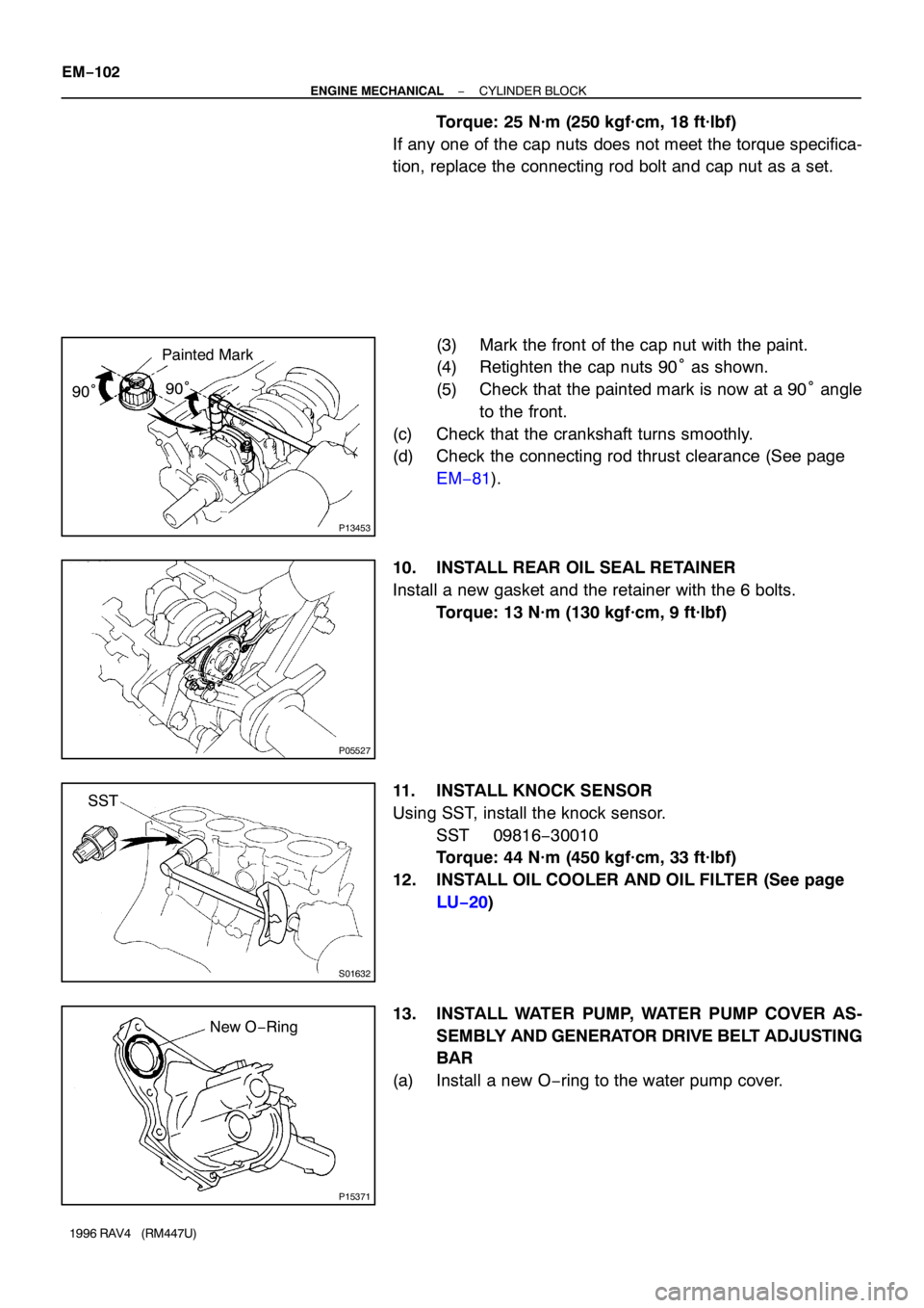
Painted Mark
90°90°
P05527
S01632
SST
P15371
New O−Ring EM−102
− ENGINE MECHANICALCYLINDER BLOCK
1996 RAV4 (RM447U)
Torque: 25 N·m (250 kgf·cm, 18 ft·lbf)
If any one of the cap nuts does not meet the torque specifica-
tion, replace the connecting rod bolt and cap nut as a set.
(3) Mark the front of the cap nut with the paint.
(4) Retighten the cap nuts 90° as shown.
(5) Check that the painted mark is now at a 90° angle
to the front.
(c) Check that the crankshaft turns smoothly.
(d) Check the connecting rod thrust clearance (See page
EM−81).
10. INSTALL REAR OIL SEAL RETAINER
Install a new gasket and the retainer with the 6 bolts.
Torque: 13 N·m (130 kgf·cm, 9 ft·lbf)
11. INSTALL KNOCK SENSOR
Using SST, install the knock sensor.
SST 09816−30010
Torque: 44 N·m (450 kgf·cm, 33 ft·lbf)
12. INSTALL OIL COOLER AND OIL FILTER (See page
LU−20)
13. INSTALL WATER PUMP, WATER PUMP COVER AS-
SEMBLY AND GENERATOR DRIVE BELT ADJUSTING
BAR
(a) Install a new O−ring to the water pump cover.
Page 798 of 1354
28
G ELECTRICAL WIRING ROUTING
Position of Parts in Engine Compartment
*1 : w/ A/C
*2 : w/o A/C
A 1 A/C Condenser Fan Motor E 1 Electronically Controlled Transmission Solenoid
A 2 A/C Magnetic Clutch and Lock Sensor E 2 Engine Coolant Temp. Sensor
A 3 A/C Triple Pressure SW (A/C Dual and Single
Pressure SW) F 1 Front Side Marker Light LH
A 4 A/C Water Temp. SW F 2 Front Side Marker Light RH
A 5 A/T Fluid Temp. SW F 3 Front Turn Signal Light LH and Front Parking
A 6 ABS Actuator Light LH
A 7 ABS Actuator F 4 Front Turn Signal Light RH and Front Parking
A 8 ABS Relay Light RH
A 9 ABS Relay F 5 Front Washer Motor
A 10 ABS Speed Sensor Front LH F 6 Front Wiper Motor
A 11 ABS Speed Sensor Front RH F 7 Fusible Link Block
B 1 Back-Up Light SW (M/T) G 1 Generator
B 2 Brake Fluid Level Warning SW G 2Generator
C 1 Center Diff. Lock Warning Buzzer SW H 1 Headlight LH
C 2 Crankshaft Position Sensor H 2 Headlight RH
C 3 Cruise Control Actuator H 3 Horn
D 1 Data Link Connector 1
Page 831 of 1354
62
CHARGING
2
5A
ALT-S
2 12 13
IG1 2
IG 2 2EA1 1 9 FROM POWER SOURCE SYSTEM (
SEE PAGE 54)
WWR-LW
W
YW
R-L
B-O R-
B R-L
W
W ARNING
ETER]
BATTERYSIBLE
NK BLOCK
TO BACK-UP LIGHT SW
R-L R-L
I 5
Y
W
A C
B B JUNCTION
CONNECTORB J10 , J11A
10A
GAUGE7. 5A
IG N 310
411FUSE
BLOCK F 8
1E 8
1B 81E 1
1C 11
L
-O
8CHARGE
LIGHT
[CO M B. M C1 1
42
FU
LI
100A ALT
80A M AIN
F 7IG L S B
IC RE G U LA TO R
B G 1 , G 2A
GENERATORA 1 B 3 B 1 B 2
Page 832 of 1354

63
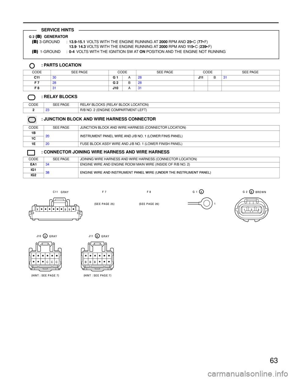
G 2 (B) GENERATOR
(B) 3-GROUND :13.9-15.1 VOLTS WITH THE ENGINE RUNNING AT 2000 RPM AND 25�C (77�F)
13.9-14.3 VOLTS WITH THE ENGINE RUNNING AT 2000 RPM AND 11 5�C (239�F)
(B) 1-GROUND :0-4 VOLTS WITH THE IGNITION SW AT ON POSITION AND THE ENGINE NOT RUNNING
: PARTS LOCATION
CODESEE PAGECODESEE PAGECODESEE PAGE
C1130G 1A28J11B31
F 728G 2B28
F 831J10A31
: RELAY BLOCKS
CODESEE PAGERELAY BLOCKS (RELAY BLOCK LOCATION)
223R/B NO. 2 (ENGINE COMPARTMENT LEFT)
: JUNCTION BLOCK AND WIRE HARNESS CONNECTOR
CODESEE PAGEJUNCTION BLOCK AND WIRE HARNESS (CONNECTOR LOCATION)
1B20INSTRUMENT PANEL WIRE AND J/B NO 1 (LOWER FINIS PANEL)1C20INSTRUMENT PANEL WIRE AND J/B NO. 1 (LOWER FINIS PANEL)
1E20FUSE BLOCK ASSY WIRE AND J/B NO. 1 (LOWER FINISH PANEL)
: CONNECTOR JOINING WIRE HARNESS AND WIRE HARNESS
CODESEE PAGEJOINING WIRE HARNESS AND WIRE HARNESS (CONNECTOR LOCATION)
EA134ENGINE WIRE AND ENGINE ROOM MAIN WIRE (INSIDE OF R/B NO. 2)
IG138ENGINE WIRE AND INSTRUMENT PANEL WIRE (UNDER THE INSTRUMENT PANEL)IG238ENGINE WIRE AND INSTRUMENT PANEL WIRE (UNDER THE INSTRUMENT PANEL)
1
123 A G 1
BBROWN G 2
(
SEE PAGE 25)(
SEE PAGE 26) F 7 F 8
9 8 X
CCC BBBC11
GRAY
(
HINT : SEE PAGE 7)(
HINT : SEE PAG E 7) AGRAY J10
BGRAY J11
SERVICE HINTS
Page 940 of 1354

K
1
234
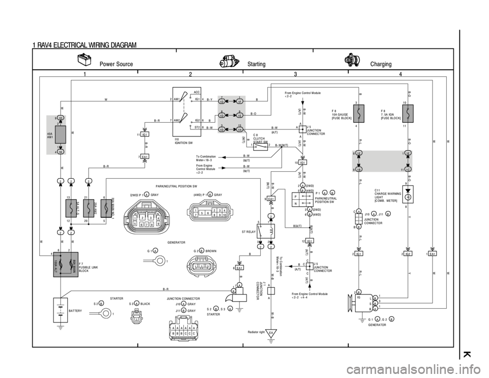
1 RAV4 ELECTRICAL WIRING DIAGRAM
2ACC
IG 1
IG 2
ST2 AM1 4
6
8 7AM2
11 IG 1
10 IG1 7 EA1
12 IG 1 1D 9
2 2 2 2
22
22 1K 4
2 5
3 7
1D
8
1D
3
1D1
1F
9
1E
13
1H
8 EA12IG1 2IG2 1EA1
1A
2B
IG
B
B
A L
S
B
EA1E 81E1
1B 81C11
8 9
P
N
1
B
W WB
WWB-RBW-BW-BR-L B-O Y B-O
R- L B B-OW W
R-L R-L
W
B B
B-W B-R
B-W B-OB
B(
A/T)
B-R B-R
W
Power Source Starting Charging
S 2 B , S 3 A
G 1 A , G 2 B STARTER
GENERATOR1
3
1 2
13 21
42310
A11 4
40A
AM1
3 0 A M A IN NO . 1
20A AM2
5A ALT-S
100A ALT 80A MAIN
F 7
FUSIBLE LINK
BLO C K
BATTERY
J 1
JUNCTION
CONNECTOR
ST R ELAY
Radiator rightF 8
10A GAUGE
[FUSE BLOCK]F 8
7. 5A IGN
[FUSE BLOCK]
C11
CHARGE WARNING
LIGHT
[C OM B . M E TER ]
Y W W
B-Y
12 20 56I10
IGN ITIO N SW
1
W
1 (
M/T) B-W
B-WB(
A/T)
9 EA1
(
A/T)B
(
A/T)
B-W
From Engine Control Module
<2-2
From E ngine Control M odule
< 2-2 < 4-4 From E ngine
Control Module
<2-2
(
M/T)
123 1B G 2 BROWN A G 1GENERATOR
1 1A S 3 BLACK B S 2A
STARTER 6CA
BBJ10 A , J11 B
JUNCTION
CONNECTOR
B
(
A/T)
B
(
A/T)C C
C
To C ombin atio n
Meter< 18-3
J 5
JUN CTION
CONNECTOR 3A
6B 5B 2A 12
B-W
(
M/T)
B
(M/T)
(
A/T)
B- W(
M/T)
B- W
(
A/T)A
A
AJ 5
JUNCTION
CONNECTOR
C 8
CLUTCH
START SW
T o C om bina tion
M eter< 18- 3
(
2WD)
(
4WD)
(
2WD)
(
4WD) P 1 A , B
PARK/NEUTRAL
POSITION SW
AAAAAA
BBBCCC 123
4
5
67891
756234
8910 A (
2WD)
P 1GRAY B(4 WD ) P 1 G R AY
B J11 GRAY PARK/NEUTRAL POSITION SW
JUNCTION CONNECTOR
A J10 GRAY
B-W (
A/T)
Page 961 of 1354

SPARK TEST
CHECK CONNECTION OF IGNITION COIL, IGNITER
AND DISTRIBUTOR CONNECTORS.
CHECK RESISTANCE OF HIGH−TENSION CORDS
TRY ANOTHER IGNITER Maximum resistance: 25 kΩ per cord (See step 2)
CHECK POWER SUPPLY TO IGNITION COIL AND
IGNITER
1. Turn ignition switch to ON.
2. Check that there is battery positive voltage at ignition coil
positive (+) terminal.
Check wiring between ECM, distributor
and igniter, and then try another ECM.
CHECK IGT SIGNAL FROM ECM
NO
BAD
OK
OK
OK
Connect securely.
Replace the cord(s).
Check wiring between ignition switch
to ignition coil and igniter.
BAD
BAD
BAD
(See page DI−100)
Cold Hot
0.36 − 0.55 Ω0.45 − 0.65 Ω CHECK RESISTANCE OF IGNITION COILOKReplace the ignition coil.
BAD Resistance: (See step 4)
Primary
Secondary
9.0 − 15.4 kΩ11.4 − 18.1 kΩ
CHECK RESISTANCE OF SIGNAL GENERATOR
Resistance: Cold HotOKReplace the distributor housing assembly.(PICKUP COIL)
(See step 5)
135 − 220 Ω175 − 255 Ω
CHECK RESISTANCE OF CRANKSHAFT POSITION
SENSOR
Resistance: Cold HotOK
Replace the crankshaft position sensor.
(See step 6)
985 − 1,600 Ω1,265 − 1,890 ΩBAD
BAD
OK
CHECK AIR GAP OF DISTRIBUTOR
Air gap: 0.2 − 0.4 mm (0.008 − 0.016 in.)Replace the distributor housing assembly.(See step 5)
BAD IG−2
− IGNITIONIGNITION SYSTEM
1996 RAV4 (RM447U)
Page 964 of 1354

B11565
B11566
B11567
− IGNITIONIGNITION SYSTEM
IG−5
1996 RAV4 (RM447U)
(d) Inspect the secondary coil resistance.
Using an ohmmeter, measure the resistance between the
positive (+) and high−tension terminals.
Secondary coil resistance:
Cold9.0 − 15.4 kΩ
Hot11.4 − 18.1 kΩ
If the resistance is not as specified, replace the ignition coil.
(e) Reconnect the high−tension cord to ignition coil.
(f) Reconnect the ignition coil connector.
5. INSPECT DISTRIBUTOR
(a) Remove the distributor cap.
Remove the 2 bolts, and disconnect the distributor cap
from the distributor housing.
(b) Remove the rotor.
(c) Inspect the air gap.
Using SST, measure the air gap between the signal rotor
and pick up coil projection.
SST 09240−00020
Air gap: 0.2 − 0.45 mm (0.008 − 0.018 in.)
If the air gap is not as specified, replace the distributor housing
assembly.
(d) Disconnect the distributor connector.
(e) Inspect the signal generator (Pickup coil) resistance.
Using an ohmmeter, measure the resistance between ter-
minals.
Pickup coil resistance:
Cold135 − 220 Ω
Hot175 − 255 Ω
If the resistance is not as specified, replace the distributor hous-
ing assembly.
(f) Reconnect the distributor connector.
(g) Reinstall the rotor.
(h) Reinstall the distributor cap.
Install a new packing and distributor cap with the 2 bolts.
Page 965 of 1354
B11568
B11569
IG−6
− IGNITIONIGNITION SYSTEM
1996 RAV4 (RM447U)
6. INSPECT CRANKSHAFT POSITION SENSOR
(a) Disconnect the crankshaft position sensor connector
from generator drive belt adjusting bar.
(b) Inspect the crankshaft position sensor resistance.
Using an ohmmeter, measure the resistance between ter-
minals.
Resistance:
Cold985 − 1,600 Ω
Hot1,265 − 1,890 Ω
If the resistance is not as specified, replace the crankshaft posi-
tion sensor.
(c) Reconnect the crankshaft position sensor connector.