Page 205 of 1399
BE1MO−01
−
BODY ELECTRICAL POWER SEAT CONTROL SYSTEM
BE−61
1199
Author�: Date�:
1996 LAND CRUISER (RM451U)
POWER SEAT CONTROL SYSTEM
LOCATION
Brought to you by BirfMark
Brought to you by BirfMark
Version 1.11 - 03/16/2010
Page 206 of 1399
BE1MP−01
BE−62
−
BODY ELECTRICAL POWER SEAT CONTROL SYSTEM
1996 LAND CRUISER (RM451U)
INSPECTION
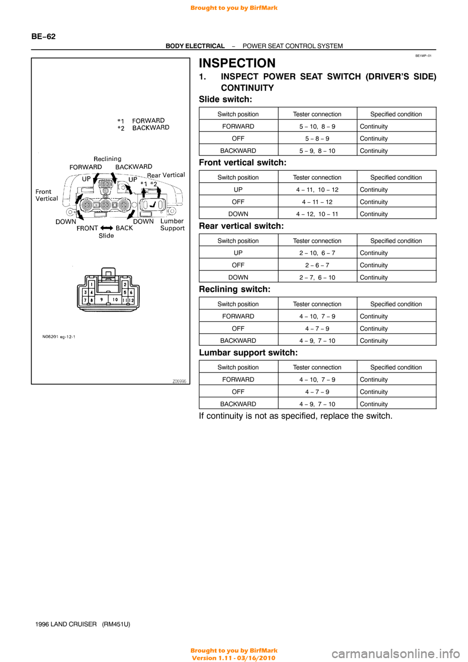
1. INSPECT POWER SEAT SWITCH (DRIVER’S SIDE) CONTINUITY
Slide switch:
Switch positionTester connectionSpecified condition
FORWARD5 − 10, 8 − 9Continuity
OFF5 − 8 − 9Continuity
BACKWARD5 − 9, 8 − 10Continuity
Front vertical switch:
Switch positionTester connectionSpecified condition
UP4 − 11, 10 − 12Continuity
OFF4 − 11 − 12Continuity
DOWN4 − 12, 10 − 11Continuity
Rear vertical switch:
Switch positionTester connectionSpecified condition
UP2 − 10, 6 − 7Continuity
OFF2 − 6 − 7Continuity
DOWN2 − 7, 6 − 10Continuity
Reclining switch:
Switch positionTester connectionSpecified condition
FORWARD4 − 10, 7 − 9Continuity
OFF4 − 7 − 9Continuity
BACKWARD4 − 9, 7 − 10Continuity
Lumbar support switch:
Switch positionTester connectionSpecified condition
FORWARD4 − 10, 7 − 9Continuity
OFF4 − 7 − 9Continuity
BACKWARD4 − 9, 7 − 10Continuity
If continuity is not as specified, replace the switch.
Brought to you by BirfMark
Brought to you by BirfMark
Version 1.11 - 03/16/2010
Page 207 of 1399
−
BODY ELECTRICAL POWER SEAT CONTROL SYSTEM
BE−63
1996 LAND CRUISER (RM451U)
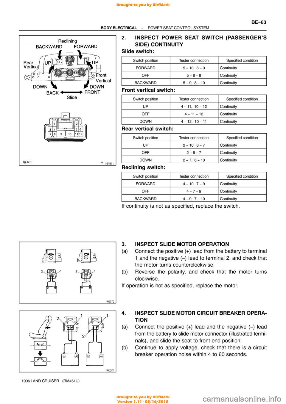
2. INSPECT POWER SEAT SWITCH (PASSENGER’S
SIDE) CONTINUITY
Slide switch:
Switch positionTester connectionSpecified condition
FORWARD5 − 10, 8 − 9Continuity
OFF5 − 8 − 9Continuity
BACKWARD5 − 9, 8 − 10Continuity
Front vertical switch:
Switch positionTester connectionSpecified condition
UP4 − 11, 10 − 12Continuity
OFF4 − 11 − 12Continuity
DOWN4 − 12, 10 − 11Continuity
Rear vertical switch:
Switch positionTester connectionSpecified condition
UP2 − 10, 6 − 7Continuity
OFF2 − 6 − 7Continuity
DOWN2 − 7, 6 − 10Continuity
Reclining switch:
Switch positionTester connectionSpecified condition
FORWARD4 − 10, 7 − 9Continuity
OFF4 − 7 − 9Continuity
BACKWARD4 − 9, 7 − 10Continuity
If continuity is not as specified, replace the switch.
3. INSPECT SLIDE MOTOR OPERATION
(a) Connect the positive (+) lead from the battery to terminal
1 and the negative ( −) lead to terminal 2, and check that
the motor turns counterclockwise.
(b) Reverse the polarity, and check that the motor turns clockwise.
If operation is not as specified, replace the motor.
4. INSPECT SLIDE MOTOR CIRCUIT BREAKER OPERA-
TION
(a) Connect the positive (+) lead and the negative ( −) lead
from the battery to slide motor connector (illustrated termi-
nals), and slide the seat to front end position.
(b) Continue to apply voltage, check that there is a circuit breaker operation noise within 4 to 60 seconds.
Brought to you by BirfMark
Brought to you by BirfMark
Version 1.11 - 03/16/2010
Page 208 of 1399
BE−64
−
BODY ELECTRICAL POWER SEAT CONTROL SYSTEM
1996 LAND CRUISER (RM451U)
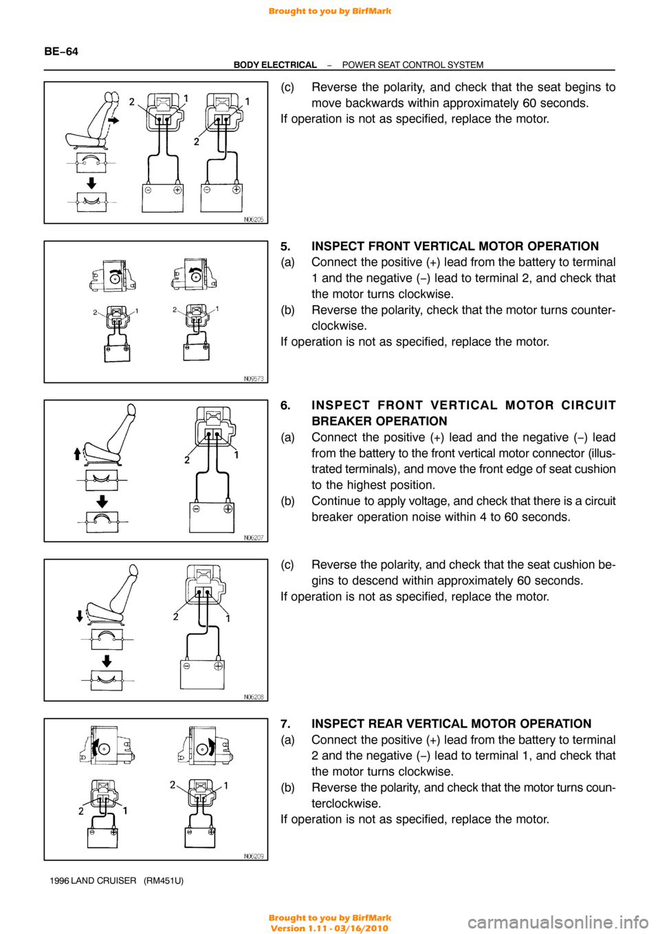
(c) Reverse the polarity, and check that the seat begins to
move backwards within approximately 60 seconds.
If operation is not as specified, replace the motor.
5. INSPECT FRONT VERTICAL MOTOR OPERATION
(a) Connect the positive (+) lead from the battery to terminal
1 and the negative ( −) lead to terminal 2, and check that
the motor turns clockwise.
(b) Reverse the polarity, check that the motor turns counter- clockwise.
If operation is not as specified, replace the motor.
6. INSPECT FRONT VERTICAL MOTOR CI RCUIT
BREAKER OPERATION
(a) Connect the positive (+) lead and the negative ( −) lead
from the battery to the front vertical motor connector (illus-
trated terminals), and move the front edge of seat cushion
to the highest position.
(b) Continue to apply voltage, and check that there is a circuit breaker operation noise within 4 to 60 seconds.
(c) Reverse the polarity , and check that the seat cushion be-
gins to descend within approximately 60 seconds.
If operation is not as specified, replace the motor.
7. INSPECT REAR VERTICAL MOTOR OPERATION
(a) Connect the positive (+) lead from the battery to terminal 2 and the negative ( −) lead to terminal 1, and check that
the motor turns clockwise.
(b) Reverse the polarity, and check that the motor turns coun-
terclockwise.
If operation is not as specified, replace the motor.
Brought to you by BirfMark
Brought to you by BirfMark
Version 1.11 - 03/16/2010
Page 209 of 1399
−
BODY ELECTRICAL POWER SEAT CONTROL SYSTEM
BE−65
1996 LAND CRUISER (RM451U)
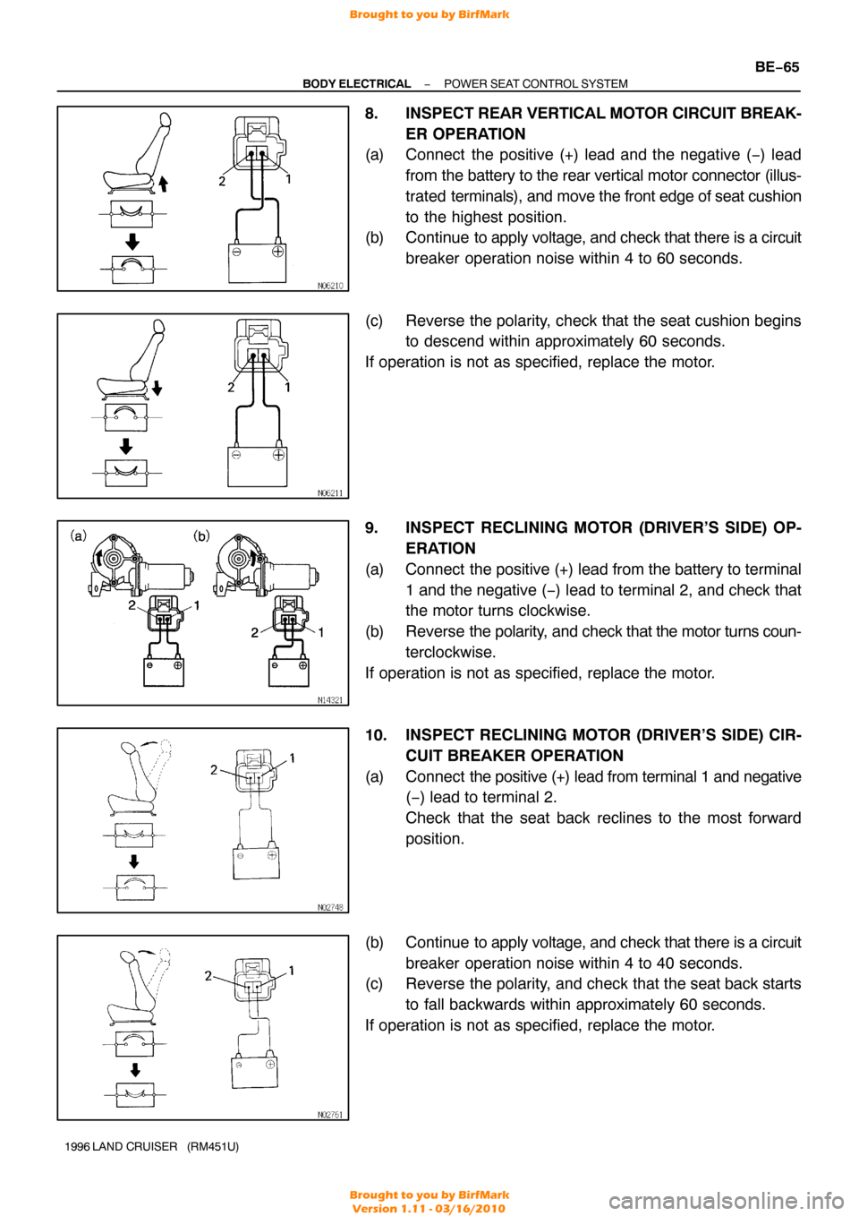
8. INSPECT REAR VERTICAL MOTOR CIRCUIT BREAK-
ER OPERATION
(a) Connect the positive (+) lead and the negative ( −) lead
from the battery to the rear vertical motor connector (illus-
trated terminals), and move the front edge of seat cushion
to the highest position.
(b) Continue to apply voltage, and check that there is a circuit
breaker operation noise within 4 to 60 seconds.
(c) Reverse the polarity, check that the seat cushion begins to descend within approximately 60 seconds.
If operation is not as specified, replace the motor.
9. INSPECT RECLINING MOTOR (DRIVER’S SIDE) OP- ERATION
(a) Connect the positive (+) lead from the battery to terminal 1 and the negative ( −) lead to terminal 2, and check that
the motor turns clockwise.
(b) Reverse the polarity, and check that the motor turns coun-
terclockwise.
If operation is not as specified, replace the motor.
10. INSPECT RECLINING MOTOR (DRIVER’S SIDE) CIR- CUIT BREAKER OPERATION
(a) Connect the positive (+) lead from terminal 1 and negative
(−) lead to terminal 2.
Check that the seat back reclines to the most forward
position.
(b) Continue to apply voltage, and check that there is a circuit breaker operation noise within 4 to 40 seconds.
(c) Reverse the polarity, and check that the seat back starts
to fall backwards within approximately 60 seconds.
If operation is not as specified, replace the motor.
Brought to you by BirfMark
Brought to you by BirfMark
Version 1.11 - 03/16/2010
Page 210 of 1399
BE−66
−
BODY ELECTRICAL POWER SEAT CONTROL SYSTEM
1996 LAND CRUISER (RM451U)
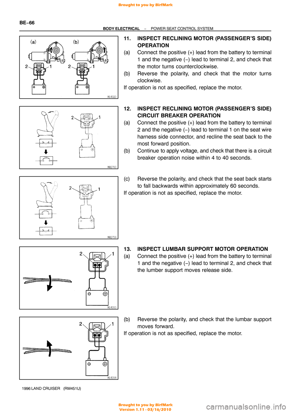
11. INSPECT RECLINING MOTOR (PASSENGER’S SIDE)
OPERATION
(a) Connect the positive (+) lead from the battery to terminal
1 and the negative ( −) lead to terminal 2, and check that
the motor turns counterclockwise.
(b) Reverse the polarity, and check that the motor turns clockwise.
If operation is not as specified, replace the motor.
12. INSPECT RECLINING MOTOR (PASSENGER’S SIDE) CIRCUIT BREAKER OPERATION
(a) Connect the positive (+) lead from the battery to terminal 2 and the negative ( −) lead to terminal 1 on the seat wire
harness side connector, and recline the seat back to the
most forward position.
(b) Continue to apply voltage, and check that there is a circuit breaker operation noise within 4 to 40 seconds.
(c) Reverse the polarity, and check that the seat back starts to fall backwards within approximately 60 seconds.
If operation is not as specified, replace the motor.
13. INSPECT LUMBAR SUPPORT MOTOR OPERATION
(a) Connect the positive (+) lead from the battery to terminal 1 and the negative ( −) lead to terminal 2, and check that
the lumber support moves release side.
(b) Reverse the polarity, and check that the lumbar support moves forward.
If operation is not as specified, replace the motor.
Brought to you by BirfMark
Brought to you by BirfMark
Version 1.11 - 03/16/2010
Page 211 of 1399
−
BODY ELECTRICAL POWER SEAT CONTROL SYSTEM
BE−67
1996 LAND CRUISER (RM451U)
14. INSPECT LUMBAR SUPPORT MOTOR CI RCUIT
BREAKER OPERATION
(a) Connect the positive (+) lead from the battery to terminal
2 and the negative (−) lead to terminal 1 on the lumbar
support motor connector and move the lumbar support to
front end position.
(b) Continue to apply voltage, and check that there is a circuit
breaker operation noise within 4 to 60 seconds.
(c) Reverse the polarity, and check that the lumbar support begins to move release side within approximately 60 se-
conds.
If operation is not as specified, replace the motor.
Brought to you by BirfMark
Brought to you by BirfMark
Version 1.11 - 03/16/2010
Page 212 of 1399
BE1MM−01
BE−68
−
BODY ELECTRICAL POWER MIRROR CONTROL SYSTEM
1206
Author�: Date�:
1996 LAND CRUISER (RM451U)
POWER MIRROR CONTROL SYSTEM
LOCATION
Brought to you by BirfMark
Brought to you by BirfMark
Version 1.11 - 03/16/2010