Page 888 of 1399
EM1EJ−01
P04409
−
ENGINE MECHANICAL CYLINDER BLOCK
EM−103
1996 LAND CRUISER (RM451U)
REASSEMBLY
HINT:
�Thoroughly clean all parts to be assembled.
�Before installing the parts, apply new engine oil to all sli-
dining and rotating surfaces.
�Replace all gaskets, O−rings and oil seals with new parts.
1. ASSEMBLE PISTON AND CONNECTING ROD
(a) Install a new snap ring on one side of the piston pin hole.
(b) Gradually heat the piston to 80 − 90° C (176 − 194°F).
(c) Coat the piston pin with engine oil.
(d) Align the front marks of the piston and connecting rod, and push in the piston pin with your thumb.
(e) Install a new snap ring on the other side of the piston pin hole.
2. INSTALL PISTON RINGS
(a) Install the oil ring expander and 2 side rails by hand.
(b) Using a piston ring expander, install the 2 compression rings with the code mark facing upward.
Code mark:
No. 11R
No. 22R
Brought to you by BirfMark
Brought to you by BirfMark
Version 1.11 - 03/16/2010
Page 889 of 1399
EM−104
−
ENGINE MECHANICAL CYLINDER BLOCK
1996 LAND CRUISER (RM451U)
(c) Position the piston rings so that the ring ends are as shown.
NOTICE:
Do not align the ring ends.
3. INSTALL BEARINGS
(a) Align the bearing claw with the groove of the connecting
rod or connecting rod cap.
(b) Install the bearings in the connecting rod and connecting rod cap.
4. INSTALL CYLINDER BLOCK ORIFICE
5. INSTALL OIL NOZZLES AND CHECK VALVES
(a) Align the pin of the oil nozzle with the pin hole of the cylin-
der block.
(b) Install the oil nozzle with the check valve. Install the 6 oil nozzles and check valves.
Torque: 25 N·m (250 kgf·cm, 18 ft·lbf)
Brought to you by BirfMark
Brought to you by BirfMark
Version 1.11 - 03/16/2010
Page 891 of 1399

(2) Install the 7 main bearing caps in their proper loca-
tions.
HINT:
Each bearing cap has a number and front mark.
(b) Ins")
EM−106
−
ENGINE MECHANICAL CYLINDER BLOCK
1996 LAND CRUISER (RM451U)
(2) Install the 7 main bearing caps in their proper loca-
tions.
HINT:
Each bearing cap has a number and front mark.
(b) Install the main bearing cap bolts.
HINT:
�The main bearing cap bolts are tightened in 2 progressive
steps (steps (b) and (d)).
�If any of the main bearing cap bolts is broken or deformed,
replace it.
(1) Apply a light coat of engine oil on the threads and
under the heads of the main bearings cap bolts.
(2) Install and uniformly tighten the 14 bolts of the main
bearing caps, in several passes, in the sequence
shown.
Torque: 74 N·m (750 kgf·cm, 54 ft·lbf)
If any one of the main bearing cap bolts does not meet the
torque specification, replace the main bearing cap bolt.
(3) Mark the front of the main bearing cap bolt withpaint.
(4) Retighten the main bearing cap bolts by 90 ° in the
numerical order shown above.
(5) Check that the painted mark is now at a 90° angle
to the front.
(c) Check that the crankshaft turns smoothly.
(d) Check that the crankshaft thrust clearance (See page EM−83 ).
10. INSTALL PISTON AND CONNECTING ROD AS- SEMBLIES
(a) Cover the connecting rod bolts with a short piece of hose
to protect the crankshaft from damage.
Brought to you by BirfMark
Brought to you by BirfMark
Version 1.11 - 03/16/2010
Page 892 of 1399

(b) Using a piston ring compressor, push the correctly num-
bered piston and connecting rod assemblies into each
cylinder wit")
−
ENGINE MECHANICAL CYLINDER BLOCK
EM−107
1996 LAND CRUISER (RM451U)
(b) Using a piston ring compressor, push the correctly num-
bered piston and connecting rod assemblies into each
cylinder with the front mark of the piston facing forward.
11. INSTALL CONNECTING ROD CAP
(a) Place the connecting rod cap on the connecting rod. (1) Match the numbered connecting rod cap with theconnecting rod.
(2) Install the connecting rod cap with the front mark facing for ward.
(b) Install the connecting rod cap nuts.
HINT:
�The connecting rod cap nuts are tightened in 2 progres-
sive steps (steps (b) and (d)).
�If any connecting rod bolt is broken or deformed, replace
it.
(1) Apply a light coat of engine oil on the threads and under the nuts of the connecting rod cap.
(2) Install and alternately tighten the nuts of the con-
necting rod cap in several passes.
Torque: 48 N·m (490 kgf·cm, 35 ft·lbf)
If any one of the connecting rod cap nuts does not meet the
torque specification, replace the connecting rod bolt and cap
nut as a set.
(3) Mark the front of the connecting rod cap nut and bolt
with paint.
(4) Retighten the connecting rod cap nuts 90 ° as
shown.
Brought to you by BirfMark
Brought to you by BirfMark
Version 1.11 - 03/16/2010
Page 893 of 1399

(5) Check that the painted mark on the nut is at 90 °
angle in relation to the mark on the bolt.
(c) Check that the")
P04615
EM−108
−
ENGINE MECHANICAL CYLINDER BLOCK
1996 LAND CRUISER (RM451U)
(5) Check that the painted mark on the nut is at 90 °
angle in relation to the mark on the bolt.
(c) Check that the crankshaft turns smoothly.
(d) Check that the connecting rod thrust clearance (See page
EM−83 ).
12. INSTALL REAR OIL SEAL RETAINER
(a) Remove any old packing (FIPG) material and be careful not to drop any oil on the contact surfaces of the retainer
and cylinder block.
�Using a razor blade and gasket scraper, remove all
the old packing (FIPG) material from the gasket sur-
faces and sealing groove.
�Thoroughly clean all components to remove all the
loose material.
�Using a non −residue solvent, clean both sealing
surfaces.
(b) Apply seal packing to the retainer as shown in the illustra-
tion.
Seal packing: Part No. 08826−00080 or equivalent
�Install a nozzle that has been cut to a 2 − 3 mm (0.08
− 0.12 in.) opening.
HINT:
Avoid applying an excessive amount to the surface.
�Parts must be assembled within 5 minutes of ap-
plication. Otherwise the material must be removed
and reapplied.
�Immediately remove nozzle from the tube and rein-
stall cap.
(c) Install the retainer with the 4 bolts. Torque: 21 N·m (210 kgf·cm, 15 ft·lbf)
13. INSTALL OIL COOLER COVER AND OIL COOLER
Install a new gasket, the oil cooler cover and oil cooler with the
10 bolts and 2 nuts. Torque: 21 N·m (210 kgf·cm, 15 ft·lbf)
Brought to you by BirfMark
Brought to you by BirfMark
Version 1.11 - 03/16/2010
Page 896 of 1399
.
Replace the distributor housing assembly.
Check wiring between ECM, ignition co")
IG0IB−02
SPARK TEST
TRY ANOTHER IGNITERNO
OK
OK
OK
OK
OK
BAD
BAD
BAD
BAD
BAD
BADConnect securely.
Replace the cord(s).
Replace the distributor housing assembly.
Check wiring between ECM, ignition coil and
igniter, and then try another ECM.
CHECK CONNECTION OF IGNITION COIL, IGNITER AND
DISTRIBUTOR CONNECTOR
CHECK RESISTANCE OF HIGH−
TENSION CORD
(See step 8)
Maximum resistance: 25 k Ω per cord
CHECK RESISTANCE OF IGNITION COIL (See step 24)
Resistance: Cold Hot
Primary 0.36 − 0.55 Ω 0.45 − 0.65 Ω
Secondary 9.0 − 15.4 kΩ 11.4 − 18.1 kΩ
CHECK AIR GAP OF DISTRIBUTOR (See step 31)
Air gap: 0.2 − 0.4 mm (0.008 −0.016 in.)
OK
CHECK RESISTANCE OF SIGNAL GENERATOR
(PICKUP COIL) (See step 32)
Resistance: Cold Hot
G1 and G− 185 − 275 Ω 240 − 325 Ω
G2 and G− 185 − 275 Ω 240 − 325 Ω
NE and G − 185 − 275 Ω 240 − 325 Ω
CHECK IGT SIGNAL FROM ECM
(See page DI−93 ) Check
wiring between ignition switch to ignition
coil and igniter.
Replace the ignition coil.
Replace the distributor housing assembly.
BAD
OK
CHECK
POWER SUPPLY TO IGNITION COIL AND IGNITER
1. Turn ignition switch to ON.
2. Check that there is battery voltage at ignition coil positive (+)
terminal.
−
IGNITION IGNITION SYSTEM
IG−1
735
Author�: Date�:
1996 LAND CRUISER (RM451U)
IGNITION SYSTEM
ON−VEHICLE INSPECTION
1. CHECK THAT SPARK OCCURS
(a) Disconnect the high −tension cords (from the ignition coil)
from the distributor cap.
(b) Hold the end approx. 12.5 mm (0.50 in.) from the body ground.
(c) Check if spark occurs while engine is being cranked.
HINT:
To prevent gasoline from being injected from injectors during
this test, crank the engine for no more than 1 − 2 seconds at a
time.
If the spark does not occur, do the test as follows:
Brought to you by BirfMark
Brought to you by BirfMark
Version 1.11 - 03/16/2010
Page 897 of 1399
P22687
P08512
IG−2
−
IGNITION IGNITION SYSTEM
736
Author�: Date�:
1996 LAND CRUISER (RM451U)
2. REMOVE NO.2 PCV HOSE
3. REMOVE AIR CLEANER HOSE
4. DISCONNECT THROTTLE CABLE
5. REMOVE NO.2 AND NO.3 CYLINDER HEAD COVERS
Remove the 4 bolts and head covers.
6. DISCONNECT HIGH −TENSION CORDS FROM SPARK
PLUGS
(a) Remove the 2 mounting bolts of the No.1 and No.2 cord clamps.
(b) Disconnect the high −tension cords at the rubber boot.
Do not pull on the cords.
NOTICE:
Pulling on or bending the cords may damage the conductor
inside.
7. DISCONNECT HIGH−TENSION CORDS FROM DIS- TRIBUTOR CAP AND IGNITION COIL
(a) Using a screwdriver, lift up the lock claw and disconnect
the holder from the distributor cap (ignition coil).
Brought to you by BirfMark
Brought to you by BirfMark
Version 1.11 - 03/16/2010
Page 898 of 1399
−
IGNITION IGNITION SYSTEM
IG−3
737
Author�: Date�:
1996 LAND CRUISER (RM451U)
(b) Disconnect the high−tension cord at the grommet.
Do not pull on the cord.
NOTICE:
Pulling on or bending the cords may damage the conductor
inside.Do not wipe any of the oil from the grommet after the
high −tension cord is disconnected.
8. INSPECT HIGH−TENSION CORD RESISTANCE
Using an ohmmeter, measure the resistance. Maximum resistance: 25 k Ω per cord
If the resistance is greater than maximum, check the terminals.
If necessary, replace the high −tension cord.
9. RECONNECT HIGH− TENSION CORDS TO DISTRIBU-
TOR CAP AND IGNITION COIL
(a) Assemble the holder and grommet.
HINT:
Connect the high− tension cords to the distributor cap as shown
in the illustration.
(b) Align the spline of the distributor (ignition coil) with the spline of the holder, and push in the cord.
Brought to you by BirfMark
Brought to you by BirfMark
Version 1.11 - 03/16/2010


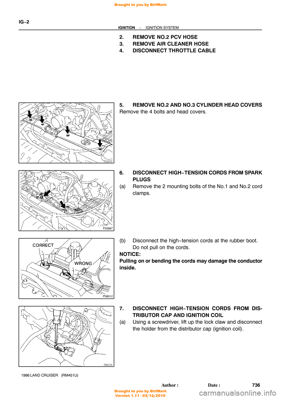
(c) Position the piston rings so that the ring ends are as shown.
NOTICE:
Do not align the ring ends.
3. INSTALL BEARINGS
(a)")