Page 1389 of 1399
Q00542
SSTSST
TF0933
TR−28
−
TRANSFER FRONT EXTENSION HOUSING
1996 LAND CRUISER (RM451U)
4. INSTALL FRONT OUTPUT SHAFT AND DRIVE
CLUTCH HUB
(a) Using SST and a press, install the front output shaft and
drive clutch hub.
SST 09316−20011, 09316 −60011 (09316−00011,
09316 −00041, 09316 −00071)
(b) Select a snap ring that will allow minimum axial play.
MarkThickness mm (in.)
A1.8 (0.0709)
B1.9 (0.0748)
C2.0 (0.0787)
D2.1 (0.0827)
E2.2 (0.0866)
(c) Using a snap ring expander, install a new snap ring.
Brought to you by BirfMark
Brought to you by BirfMark
Version 1.11 - 03/16/2010
Page 1390 of 1399
TR0BH−01
Q08383
Center Differential Control
Couping Assembly
Snap ring Vehicle Speed sensor
Drive Gear Ball Bearing
� Snap Ring
Snap Ring
Oil Pump Plate
Drive Rotor
Oil Pump Cover
Rear Extension housing
Oil Pump Drive Shaft Ball
Spring �
Screw Plug
Valve Seat
�
Dust Deflector
� Oil Seal Seal Ring
Rear Output Shaft
� Non− reusable Part
� Precoated part Separator
Driven Rotor
−
TRANSFER REAR EXTENSION HOUSING
TR−29
839
Author�: Date�:
1996 LAND CRUISER (RM451U)
REAR EXTENSION HOUSING
COMPONENTS
Brought to you by BirfMark
Brought to you by BirfMark
Version 1.11 - 03/16/2010
Page 1392 of 1399
TF0959
SST
Q08385
Q08481
SST
−
TRANSFER REAR EXTENSION HOUSING
TR−31
1996 LAND CRUISER (RM451U)
9. REMOVE REAR OUTPUT SHAFT
(a) Using a snap ring expander, remove the snap ring.
(b) Using SST and a hammer, remove the rear output shaft.
SST 09325−12010
(c) Remove the 2 seal rings from the rear output shaft.
10. REMOVE DUST DEFLECTOR
(a) Using a screwdriver and hammer, remove the rear exten-
sion housing dust deflector.
(b) Using a screwdriver and hammer, remove the rear output
shaft dust deflector.
11. REMOVE OIL SEAL
Using a screwdriver, pry out the oil seal from the rear extension
housing.
12. REMOVE BALL BEARING
(a) Using a screwdriver, remove the snap ring.
(b) Using SST and a press, remove the ball bearing to the rear extension housing.
SST 09316−60011 (09316 −00011, 09316−00021)
Brought to you by BirfMark
Brought to you by BirfMark
Version 1.11 - 03/16/2010
Page 1393 of 1399

TR0BJ−01
Q02615
Q02616
Q02617
TR−32
−
TRANSFER REAR EXTENSION HOUSING
1996 LAND CRUISER (RM451U)
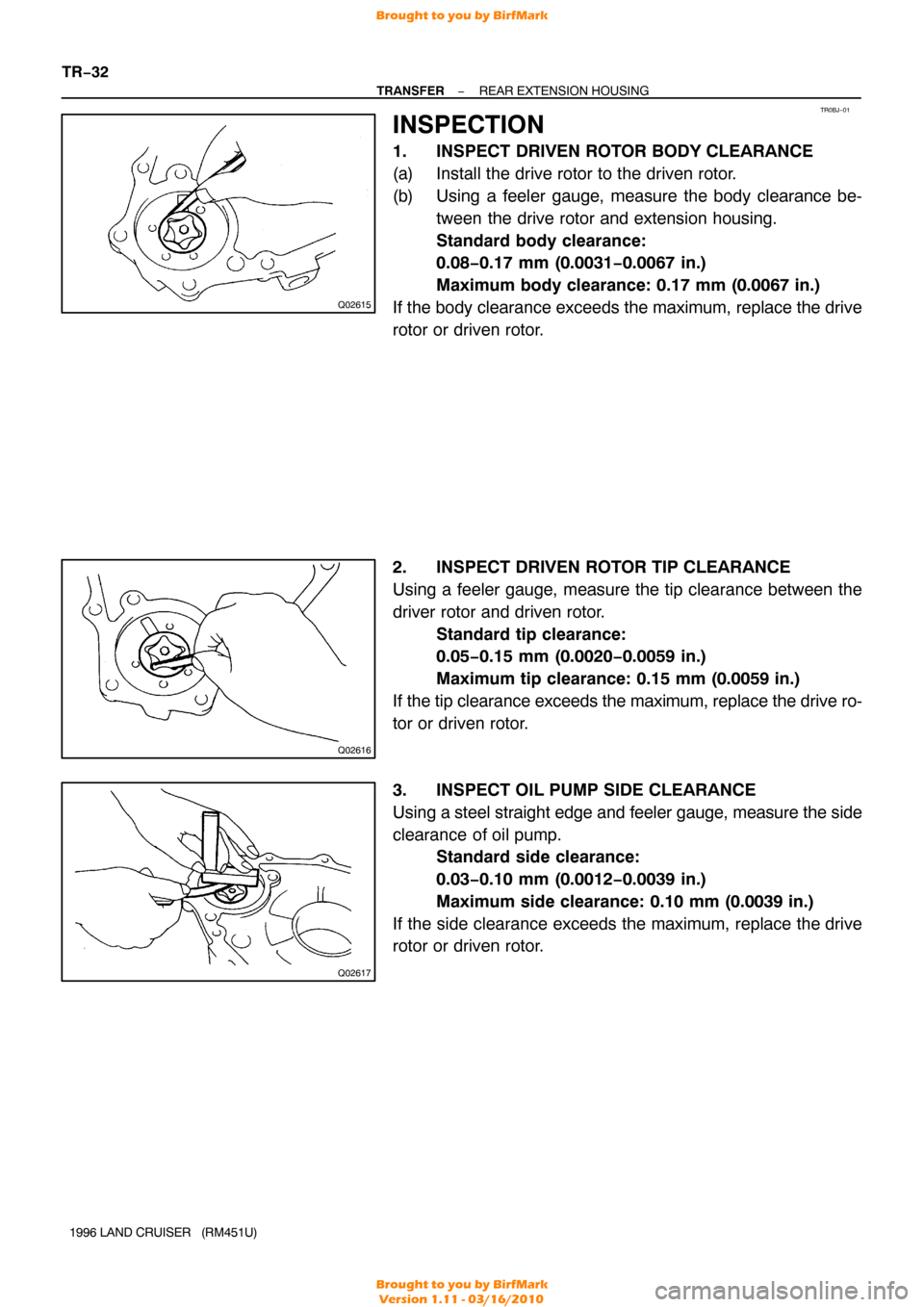
INSPECTION
1. INSPECT DRIVEN ROTOR BODY CLEARANCE
(a) Install the drive rotor to the driven rotor.
(b) Using a feeler gauge, measure the body clearance be- tween the drive rotor and extension housing.
Standard body clearance:
0.08−0.17 mm (0.0031 −0.0067 in.)
Maximum body clearance: 0.17 mm (0.0067 in.)
If the body clearance exceeds the maximum, replace the drive
rotor or driven rotor.
2. INSPECT DRIVEN ROTOR TIP CLEARANCE
Using a feeler gauge, measure the tip clearance between the
driver rotor and driven rotor. Standard tip clearance:
0.05−0.15 mm (0.0020 −0.0059 in.)
Maximum tip clearance: 0.15 mm (0.0059 in.)
If the tip clearance exceeds the maximum, replace the drive ro-
tor or driven rotor.
3. INSPECT OIL PUMP SIDE CLEARANCE
Using a steel straight edge and feeler gauge, measure the side
clearance of oil pump. Standard side clearance:
0.03−0.10 mm (0.0012 −0.0039 in.)
Maximum side clearance: 0.10 mm (0.0039 in.)
If the side clearance exceeds the maximum, replace the drive
rotor or driven rotor.
Brought to you by BirfMark
Brought to you by BirfMark
Version 1.11 - 03/16/2010
Page 1394 of 1399
TR0CO−01
TF0964
SST
TF0962
Q08482
SST
TF0967
SST
Q08482
SST
−
TRANSFER REAR EXTENSION HOUSING
TR−33
1996 LAND CRUISER (RM451U)
REASSEMBLY
HINT:
Coat all of the sliding and rotating surfaces with gear oil before
assembly.
1. INSTALL BALL BEARING
(a) Using SST and a press, install the ball bearing.
SST 09316−60011 (09316 −00011, 09316−00031)
(b) Select a snap ring that will allow minimum axial play.
MarkThickness mm (in.)
A1.7 (0.0669)
B1.8 (0.0709)
(c) Using a screwdriver, install a new snap ring.
2. INSTALL DUST DEFLECTOR
(a) Using SST and a hammer, install a new rear extension housing dust deflector.
SST 09316−60011 (09316 −00011, 09316−00041)
(b) Using SST and a press, install a new rear output shaft dust deflector.
SST 09316−20011, 09316 −60011 (09316−00011)
3. INSTALL OIL SEAL
Using SST and a hammer, drive in a new oil seal. SST 09316−60011 (09316 −00011, 09316−00031)
Brought to you by BirfMark
Brought to you by BirfMark
Version 1.11 - 03/16/2010
Page 1395 of 1399

TF0969
SST
TF0958
Q07138
Q02549
Q08384
TR−34
−
TRANSFER REAR EXTENSION HOUSING
1996 LAND CRUISER (RM451U)
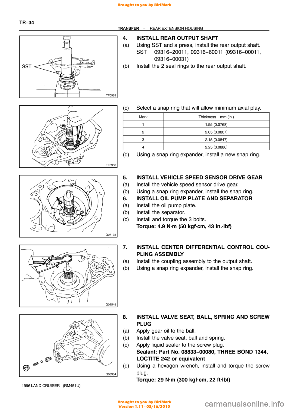
4. INSTALL REAR OUTPUT SHAFT
(a) Using SST and a press, install the rear output shaft.
SST 09316−20011, 09316 −60011 (09316−00011,
09316 −00031)
(b) Install the 2 seal rings to the rear output shaft.
(c) Select a snap ring that will allow minimum axial play.
MarkThickness mm (in.)
11.95 (0.0768)
22.05 (0.0807)
32.15 (0.0847)
42.25 (0.0886)
(d) Using a snap ring expander, install a new snap ring.
5. INSTALL VEHICLE SPEED SENSOR DRIVE GEAR
(a) Install the vehicle speed sensor drive gear.
(b) Using a snap ring expander, install the snap ring.
6. INSTALL OIL PUMP PLATE AND SEPARATOR
(a) Install the oil pump plate.
(b) Install the separator.
(c) Install and torque the 3 bolts. Torque: 4.9 N·m (50 kgf·cm, 43 in.·lbf)
7. INSTALL CENTER DIFFERENTIAL CONTROL COU- PLING ASSEMBLY
(a) Install the coupling assembly to the output shaft.
(b) Using a snap ring expander, install the snap ring.
8. INSTALL VALVE SEAT, BALL, SPRING AND SCREW PLUG
(a) Apply gear oil to the ball.
(b) Install the valve seat, ball and spring.
(c) Apply liquid sealer to the screw plug.
Sealant: Part No. 08833−00080, THREE BOND 1344,
LOCTITE 242 or equivalent
(d) Using a hexagon wrench, install and torque the screw plug.
Torque: 29 N·m (300 kgf·cm, 22 ft·lbf)
Brought to you by BirfMark
Brought to you by BirfMark
Version 1.11 - 03/16/2010
Page 1398 of 1399

Q02622
Light upGoes off
L
NH
DIFF LOCK
DIFF LOCK
TR0BM−03
Z15367
Relay Side
V01699
V06651
−
TRANSFER MOTOR SHIFT CONTROL SYSTEM
TR−37
1996 LAND CRUISER (RM451U)
INSPECTION
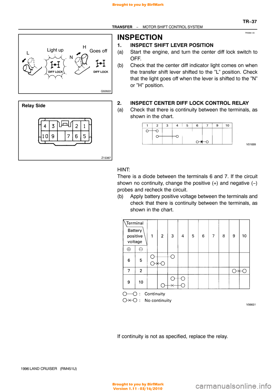
1. INSPECT SHIFT LEVER POSITION
(a) Start the engine, and turn the center diff lock switch to
OFF.
(b) Check that the center diff indicator light comes on when the transfer shift lever shifted to the ”L” position. Check
that the light goes off when the lever is shifted to the ”N”
or ”H” position.
2. INSPECT CENTER DIFF LOCK CONTROL RELAY
(a) Check that there is continuity between the terminals, as shown in the chart.
HINT:
There is a diode between the terminals 6 and 7. If the circuit
shown no continuity, change the positive (+) and negative ( −)
probes and recheck the circuit.
(b) Apply battery positive voltage between the terminals and check that there is continuity between the terminals, as
shown in the chart.
If continuity is not as specified, replace the relay.
Brought to you by BirfMark
Brought to you by BirfMark
Version 1.11 - 03/16/2010
Page 1399 of 1399
TR−38
−
TRANSFER MOTOR SHIFT CONTROL SYSTEM
1996 LAND CRUISER (RM451U)
3. INSPECT MOTOR ACTUATOR
(a) Measure the resistance between the terminals 2 and 3.
Standard resistance: 0.3 − 100 Ω
(b) Measure the resistance between the terminals 2 or 3 and
body ground.
Standard resistance: More than 0.5 MΩ
If the resistance value is not as specified, replace the motor ac-
tuator.
Brought to you by BirfMark
Brought to you by BirfMark
Version 1.11 - 03/16/2010