Page 1358 of 1399
V06796
−
STARTING STARTER
ST−13
1996 LAND CRUISER (RM451U)
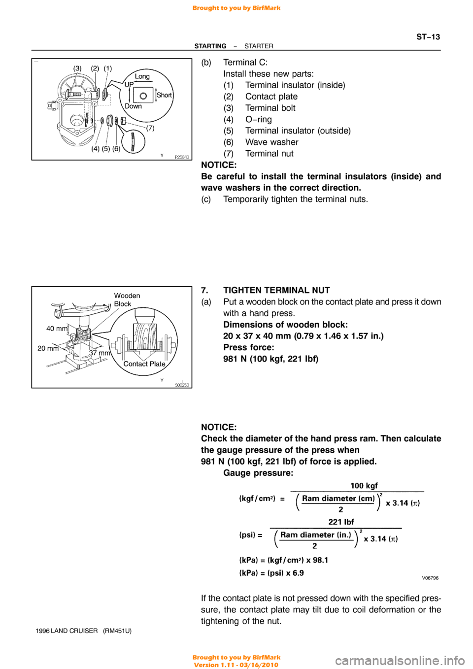
(b) Terminal C:
Install these new parts:
(1) Terminal insulator (inside)
(2) Contact plate
(3) Terminal bolt
(4) O−ring
(5) Terminal insulator (outside)
(6) Wave washer
(7) Terminal nut
NOTICE:
Be careful to install the terminal insulators (inside) and
wave washers in the correct direction.
(c) Temporarily tighten the terminal nuts.
7. TIGHTEN TERMINAL NUT
(a) Put a wooden block on the contact plate and press it down with a hand press.
Dimensions of wooden block:
20 x 37 x 40 mm (0.79 x 1.46 x 1.57 in.)
Press force:
981 N (100 kgf, 221 lbf)
NOTICE:
Check the diameter of the hand press ram. Then calculate
the gauge pressure of the press when
981 N (100 kgf, 221 lbf) of force is applied. Gauge pressure:
If the contact plate is not pressed down with the specified pres-
sure, the contact plate may tilt due to coil deformation or the
tightening of the nut.
Brought to you by BirfMark
Brought to you by BirfMark
Version 1.11 - 03/16/2010
Page 1361 of 1399
ST08H−03
P23047
Terminal CBattery
Terminal 50
P23049
Disconnect
Battery
P23048
DIsconnect
Battery
P23050
Terminal 30 AmmeterBattery
Terminal 50
ST−16
−
STARTING STARTER
1996 LAND CRUISER (RM451U)
TEST
NOTICE:
These tests must be performed within 3 to 5 seconds to
avoid burning out the coil.
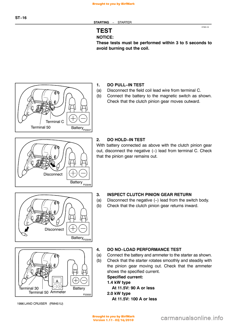
1. DO PULL−IN TEST
(a) Disconnect the field coil lead wire from terminal C.
(b) Connect the battery to the magnetic switch as shown.
Check that the clutch pinion gear moves outward.
2. DO HOLD−IN TEST
With battery connected as above with the clutch pinion gear
out, disconnect the negative ( −) lead from terminal C. Check
that the pinion gear remains out.
3. INSPECT CLUTCH PINION GEAR RETURN
(a) Disconnect the negative ( −) lead from the switch body.
(b) Check that the clutch pinion gear returns inward.
4. DO NO−LOAD PERFORMANCE TEST
(a) Connect the battery and ammeter to the starter as shown.
(b) Check that the starter rotates smoothly and steadily with
the pinion gear moving out. Check that the ammeter
shows the specified current.
Specified current:
1.4 kW type
At 11.5V: 90 A or less
2.0 kW type
At 11.5V: 100 A or less
Brought to you by BirfMark
Brought to you by BirfMark
Version 1.11 - 03/16/2010
Page 1366 of 1399
Q04610
Q00541
Front
Q02950
Q07125
FIPG
−
TRANSFER TRANSFER ASSEMBLY
TR−5
1996 LAND CRUISER (RM451U)
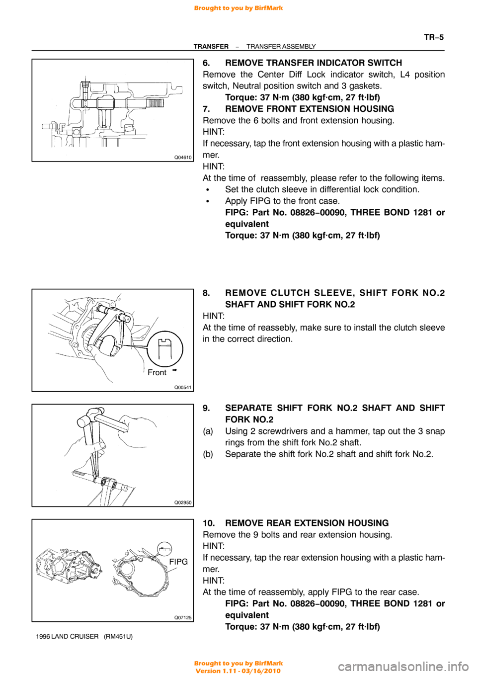
6. REMOVE TRANSFER INDICATOR SWITCH
Remove the Center Diff Lock indicator switch, L4 position
switch, Neutral position switch and 3 gaskets.
Torque: 37 N·m (380 kgf·cm, 27 ft·lbf)
7. REMOVE FRONT EXTENSION HOUSING
Remove the 6 bolts and front extension housing.
HINT:
If necessary, tap the front extension housing with a plastic ham-
mer.
HINT:
At the time of reassembly, please refer to the following items.
�Set the clutch sleeve in differential lock condition.
�Apply FIPG to the front case.
FIPG: Part No. 08826−00090, THREE BOND 1281 or
equivalent
Torque: 37 N·m (380 kgf·cm, 27 ft·lbf)
8. REMOVE CLUTCH SLEEVE, SHIFT FORK NO.2 SHAFT AND SHIFT FORK NO.2
HINT:
At the time of reassebly, make sure to install the clutch sleeve
in the correct direction.
9. SEPARATE SHIFT FORK NO.2 SHAFT AND SHIFT FORK NO.2
(a) Using 2 screwdrivers and a hammer, tap out the 3 snap rings from the shift fork No.2 shaft.
(b) Separate the shift fork No.2 shaft and shift fork No.2.
10. REMOVE REAR EXTENSION HOUSING
Remove the 9 bolts and rear extension housing.
HINT:
If necessary, tap the rear extension housing with a plastic ham-
mer.
HINT:
At the time of reassembly, apply FIPG to the rear case. FIPG: Part No. 08826−00090, THREE BOND 1281 or
equivalent
Torque: 37 N·m (380 kgf·cm, 27 ft·lbf)
Brought to you by BirfMark
Brought to you by BirfMark
Version 1.11 - 03/16/2010
Page 1367 of 1399
Z18976
B
Z18977
C
TR−6
−
TRANSFER TRANSFER ASSEMBLY
1996 LAND CRUISER (RM451U)
11. REMOVE RETAINER FROM REAR CASE
Remove the 5 bolts and retainer.
Torque: 39 N·m (400 kgf·cm, 28 ft·lbf)
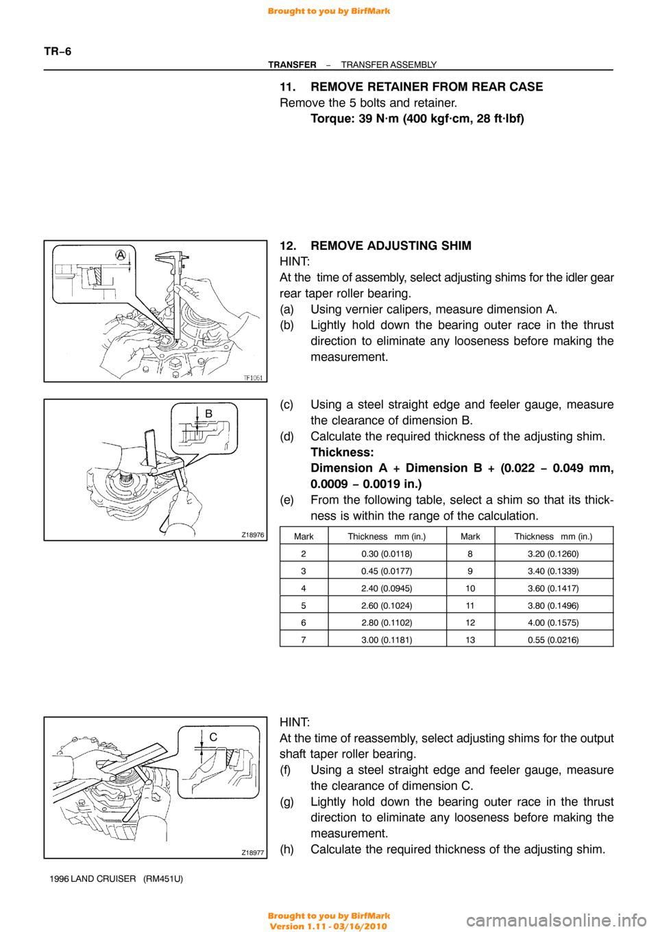
12. REMOVE ADJUSTING SHIM
HINT:
At the time of assembly, select adjusting shims for the idler gear
rear taper roller bearing.
(a) Using vernier calipers, measure dimension A.
(b) Lightly hold down the bearing outer race in the thrust direction to eliminate any looseness before making the
measurement.
(c) Using a steel straight edge and feeler gauge, measure the clearance of dimension B.
(d) Calculate the required thickness of the adjusting shim. Thickness:
Dimension A + Dimension B + (0.022 − 0.049 mm,
0.0009 − 0.0019 in.)
(e) From the following table, select a shim so that its thick- ness is within the range of the calculation.
MarkThickness mm (in.)MarkThickness mm (in.)
20.30 (0.0118)83.20 (0.1260)
30.45 (0.0177)93.40 (0.1339)
42.40 (0.0945)103.60 (0.1417)
52.60 (0.1024)113.80 (0.1496)
62.80 (0.1 102)124.00 (0.1575)
73.00 (0.1181)130.55 (0.0216)
HINT:
At the time of reassembly, select adjusting shims for the output
shaft taper roller bearing.
(f) Using a steel straight edge and feeler gauge, measure
the clearance of dimension C.
(g) Lightly hold down the bearing outer race in the thrust direction to eliminate any looseness before making the
measurement.
(h) Calculate the required thickness of the adjusting shim.
Brought to you by BirfMark
Brought to you by BirfMark
Version 1.11 - 03/16/2010
Page 1368 of 1399
Q07126
FIPG
Q08404
FIPG
A
−
TRANSFER TRANSFER ASSEMBLY
TR−7
1996 LAND CRUISER (RM451U)
Thickness:
Dimension C + (0. 014 − 0.039 mm, 0.0006 − 0.0015 in.)
(i) From the following table, select a shim so that its thick-
ness is within the range of the calculation.
MarkThickness mm (in.)MarkThickness mm (in.)
B0.30 (0.0118)H1.80 (0.0709)
C0.45 (0.0177)J2.00 (0.0787)
D1.00 (0.0394)K2.20 (0.0866)
E1.20 (0.0472)L2.40 (0.0945)
F1.40 (0.0551)M2.60 (0.1024)
G1.60 (0.0630)N0.55 (0.0216)
13. REMOVE OIL STRAINER FROM REAR CASE
Remove the 2 set bolts and oil strainer.Torque: 4.9 N·m (50 kgf·cm, 43 in.·lbf)
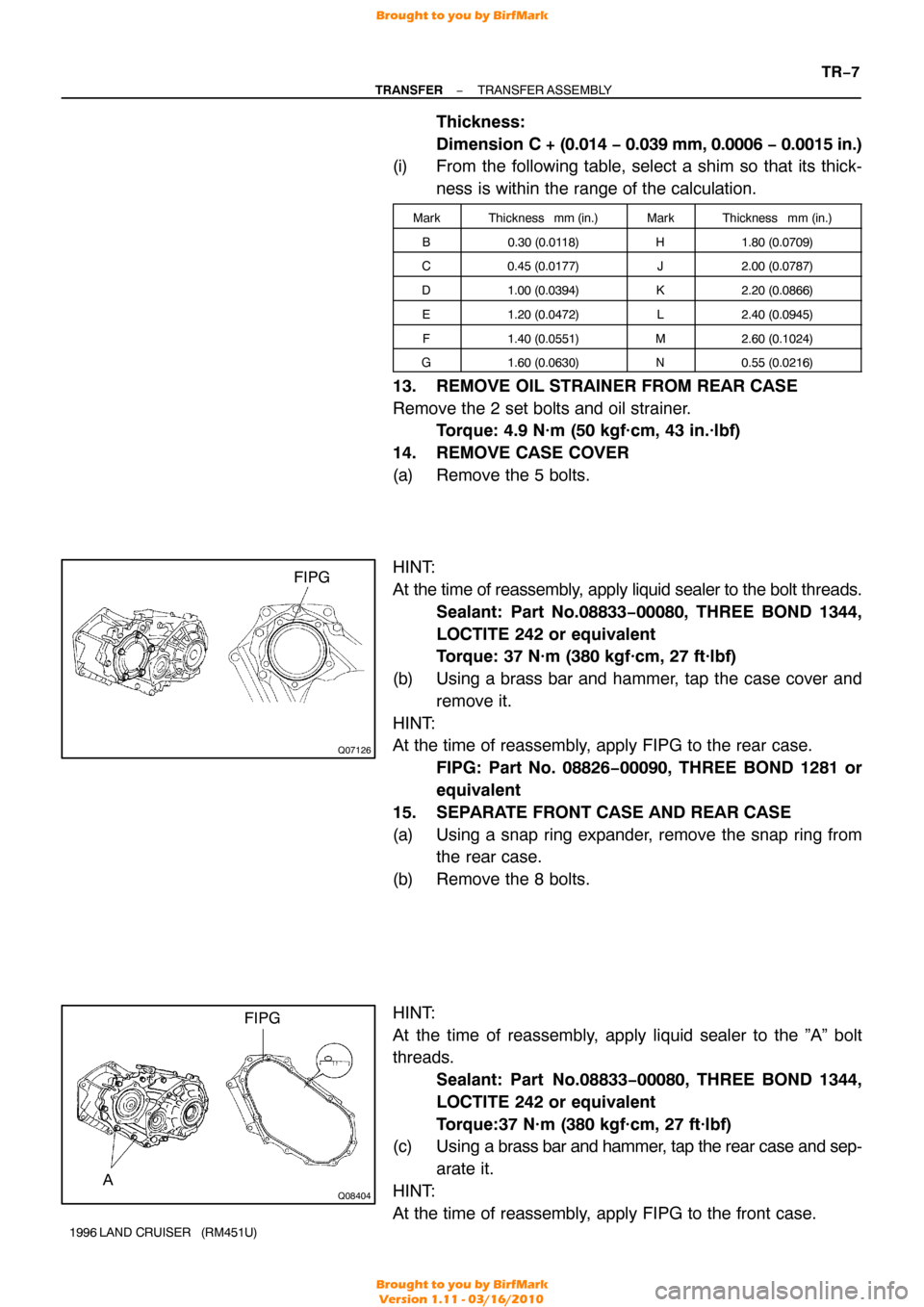
14. REMOVE CASE COVER
(a) Remove the 5 bolts.
HINT:
At the time of reassembly, apply liquid sealer to the bolt threads.
Sealant: Part No.08833−00080, THREE BOND 1344,
LOCTITE 242 or equivalent
Torque: 37 N·m (380 kgf·cm, 27 ft·lbf)
(b) Using a brass bar and hammer, tap the case cover and remove it.
HINT:
At the time of reassembly, apply FIPG to the rear case. FIPG: Part No. 08826−00090, THREE BOND 1281 or
equivalent
15. SEPARATE FRONT CASE AND REAR CASE
(a) Using a snap ring expander, remove the snap ring from the rear case.
(b) Remove the 8 bolts.
HINT:
At the time of reassembly, apply liquid sealer to the ”A” bolt
threads. Sealant: Part No.08833 −00080, THREE BOND 1344,
LOCTITE 242 or equivalent
Torque:37 N·m (380 kgf·cm, 27 ft·lbf)
(c) Using a brass bar and hammer, tap the rear case and sep-
arate it.
HINT:
At the time of reassembly, apply FIPG to the front case.
Brought to you by BirfMark
Brought to you by BirfMark
Version 1.11 - 03/16/2010
Page 1370 of 1399
Q07131
SST
TF0867
I19645
Push
Free
−
TRANSFER TRANSFER ASSEMBLY
TR−9
1996 LAND CRUISER (RM451U)
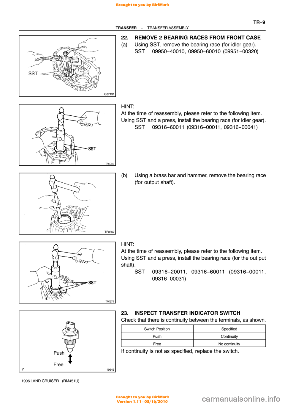
22. REMOVE 2 BEARING RACES FROM FRONT CASE
(a) Using SST, remove the bearing race (for idler gear).
SST 09950−40010, 09950 −60010 (09951−00320)
HINT:
At the time of reassembly, please refer to the following item.
Using SST and a press, install the bearing race (for idler gear).
SST 09316−60011 (09316 −00011, 09316−00041)
(b) Using a brass bar and hammer, remove the bearing race
(for output shaft).
HINT:
At the time of reassembly, please refer to the following item.
Using SST and a press, install the bearing race (for the out put
shaft). SST 09316 −20011, 09316 −60011 (09316 −00011,
09316 −00031)
23. INSPECT TRANSFER INDICATOR SWITCH
Check that there is continuity between the terminals, as shown.
Switch PositionSpecified
PushContinuity
FreeNo continuity
If continuity is not as specified, replace the switch.
Brought to you by BirfMark
Brought to you by BirfMark
Version 1.11 - 03/16/2010
Page 1375 of 1399
TR0B7−01
Q00533
TR−14
−
TRANSFER INPUT SHAFT
1996 LAND CRUISER (RM451U)
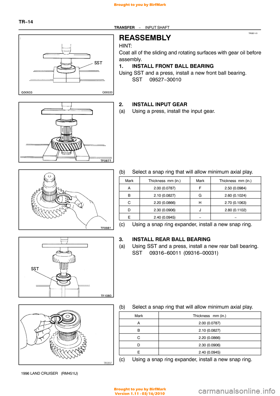
REASSEMBLY
HINT:
Coat all of the sliding and rotating surfaces with gear oil before
assembly.
1. INSTALL FRONT BALL BEARING
Using SST and a press, install a new front ball bearing. SST 09527−30010
2. INSTALL INPUT GEAR
(a) Using a press, install the input gear.
(b) Select a snap ring that will allow minimum axial play.
MarkThickness mm (in.)MarkThickness mm (in.)
A2.00 (0.0787)F2.50 (0.0984)
B2.10 (0.0827)G2.60 (0.1024)
C2.20 (0.0866)H2.70 (0.1063)
D2.30 (0.0906)J2.80 (0.1 102)
E2.40 (0.0945)−−
(c) Using a snap ring expander, install a new snap ring.
3. INSTALL REAR BALL BEARING
(a) Using SST and a press, install a new rear ball bearing.
SST 09316−60011 (09316 −00031)
(b) Select a snap ring that will allow minimum axial play.
MarkThickness mm (in.)
A2.00 (0.0787)
B2.10 (0.0827)
C2.20 (0.0866)
D2.30 (0.0906)
E2.40 (0.0945)
(c) Using a snap ring expander, install a new snap ring.
Brought to you by BirfMark
Brought to you by BirfMark
Version 1.11 - 03/16/2010
Page 1377 of 1399
TR0B9−01
TF0887
TF0888
Q07132
SST
Q07100
Socket Wrench
TR−16
−
TRANSFER IDLER GEAR
1996 LAND CRUISER (RM451U)
DISASSEMBLY
1. INSPECT IDLER LOW GEAR RADIAL AND THRUST
CLEARANCE
(a) Using a feeler gauge, measure the idler low gear thrust clearance.
Standard clearance:
0.125−0.275 mm (0.0049 −0.0108 in.)
Maximum clearance:
0.275 mm (0.0108 in.)
(b) Using a dial indicator, measure the idler low gear radial clearance.
Standard clearance:
0.015−0.068 mm (0.0006 −0.0027 in.)
Maximum clearance:
0.068 mm (0.0027 in.)
2. REMOVE FRONT TAPER ROLLER BEARING
Using SST, remove the front taper roller bearing. SST 09950−40010
3. REMOVE REAR TAPER ROLLER BEARING
Using SST, a press and socket wrench, remove the rear taper
roller bearing. SST 09950−00020
4. REMOVE IDLER LOW GEAR AND NEEDLE ROLLER BEARING FROM IDLER GEAR
5. REMOVE HIGH AND LOW CLUTCH SLEEVE FROM IDLER GEAR
Brought to you by BirfMark
Brought to you by BirfMark
Version 1.11 - 03/16/2010