Page 1335 of 1399
SS−34
−
SERVICE SPECIFICATIONS SUSPENSION AND AXLE
1996 LAND CRUISER (RM451U)
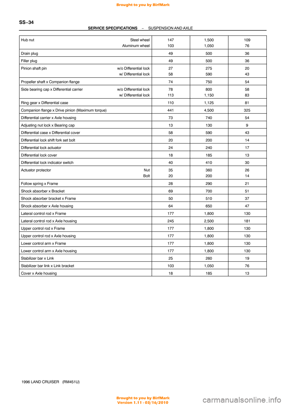
Hub nut
Steel wheel
Aluminum wheel
147
1031,500
1,050109 76
Drain plug4950036
Filler plug4950036
Pinion shaft pin w/o Differential lock
w/ Differential lock27
58275
59020
43
Propeller shaft x Companion flange7475054
Side bearing cap x Differential carrier w/o Differential lock
w/ Differential lock78
11 3800
1,15058
83
Ring gear x Differential case11 01,12581
Companion flange x Drive pinion (Maximum torque)4414,500325
Differential carrier x Axle housing7374054
Adjusting nut lock x Bearing cap131309
Differential case x Differential cover5859043
Differential lock shift fork set bolt2020014
Differential lock actuator2424017
Differential lock cover1818513
Differential lock indicator switch4041030
Actuator protector Nut
Bolt35
20360
20026
14
Follow spring x Frame2829021
Shock absorber x Bracket6970051
Shock absorber bracket x Frame5051037
Shock absorber x Axle housing6465047
Lateral control rod x Frame1771,800130
Lateral control rod x Axle housing2452,500181
Upper control rod x Frame1771,800130
Upper control rod x Axle housing1771,800130
Lower control arm x Frame1771,800130
Lower control arm x Axle housing1771,800130
Stabilizer bar x Link2526019
Stabilizer bar link x Link bracket1031,05076
Cover x Axle housing1818513
Brought to you by BirfMark
Brought to you by BirfMark
Version 1.11 - 03/16/2010
Page 1339 of 1399
SS1EH−02
SS−38
−
SERVICE SPECIFICATIONS STEERING
1996 LAND CRUISER (RM451U)
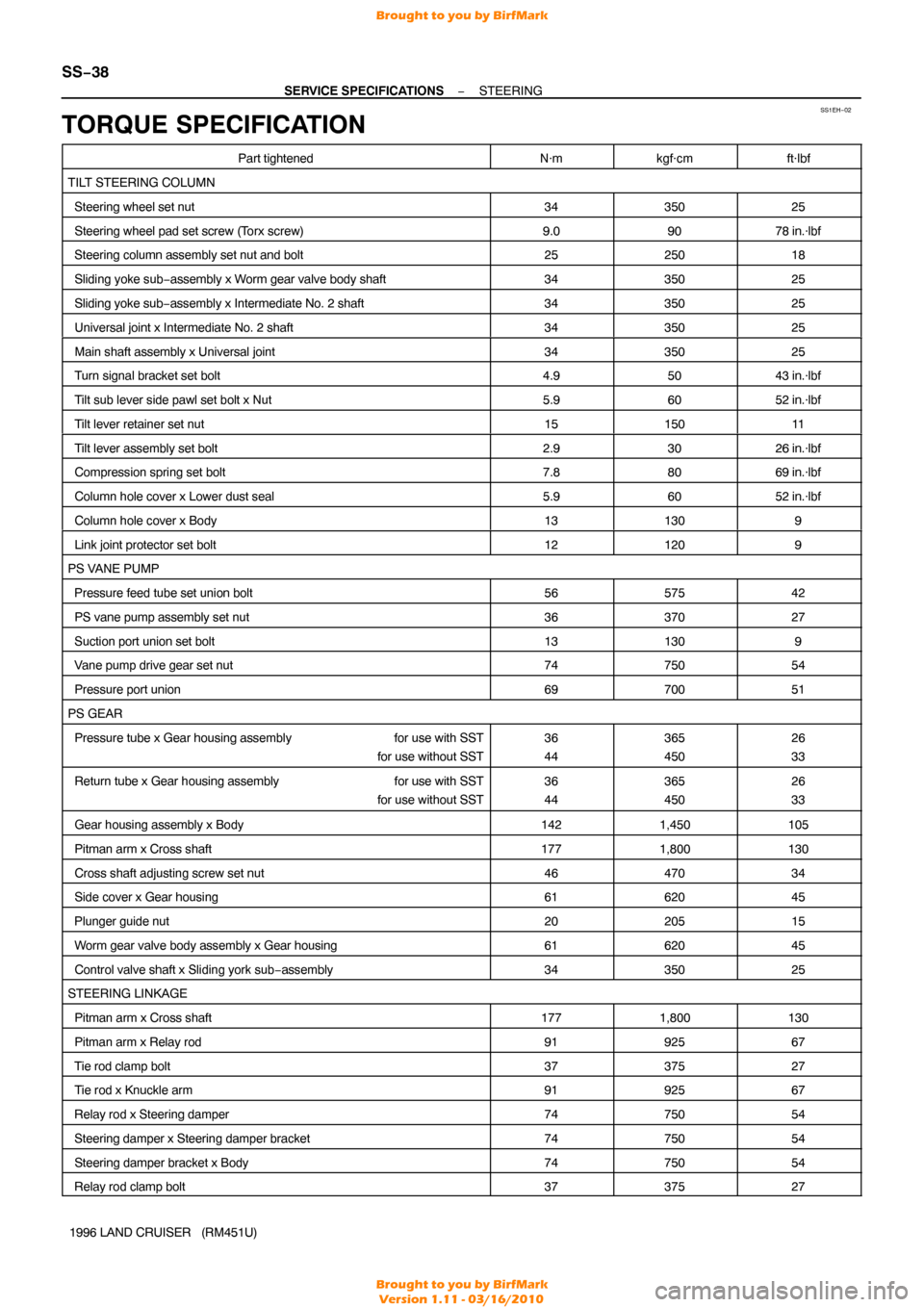
TORQUE SPECIFICATION
Part tightenedN·mkgf·cmft·lbf
TILT STEERING COLUMN
Steering wheel set nut3435025
Steering wheel pad set screw (T orx screw)9.09078 in.·lbf
Steering column assembly set nut and bolt2525018
Sliding yoke sub−assembly x Worm gear valve body shaft3435025
Sliding yoke sub −assembly x Intermediate No. 2 shaft3435025
Universal joint x Intermediate No. 2 shaft3435025
Main shaft assembly x Universal joint3435025
Turn signal bracket set bolt4.95043 in.·lbf
Tilt sub lever side pawl set bolt x Nut5.96052 in.·lbf
Tilt lever retainer set nut1515011
Tilt lever assembly set bolt2.93026 in.·lbf
Compression spring set bolt7.88069 in.·lbf
Column hole cover x Lower dust seal5.96052 in.·lbf
Column hole cover x Body131309
Link joint protector set bolt121209
PS VANE PUMP
Pressure feed tube set union bolt5657542
PS vane pump assembly set nut3637027
Suction port union set bolt131309
Vane pump drive gear set nut7475054
Pressure port union6970051
PS GEAR
Pressure tube x Gear housing assembly for use with SST
for use without SST36
44365
45026
33
Return tube x Gear housing assembly for use with SST
for use without SST36
44365
45026
33
Gear housing assembly x Body1421,450105
Pitman arm x Cross shaft1771,800130
Cross shaft adjusting screw set nut4647034
Side cover x Gear housing6162045
Plunger guide nut2020515
Worm gear valve body assembly x Gear housing6162045
Control valve shaft x Sliding york sub −assembly3435025
STEERING LINKAGE
Pitman arm x Cross shaft1771,800130
Pitman arm x Relay rod9192567
Tie rod clamp bolt3737527
Tie rod x Knuckle arm9192567
Relay rod x Steering damper7475054
Steering damper x Steering damper bracket7475054
Steering damper bracket x Body7475054
Relay rod clamp bolt3737527
Brought to you by BirfMark
Brought to you by BirfMark
Version 1.11 - 03/16/2010
Page 1341 of 1399
SS1EJ−02
SS−40
−
SERVICE SPECIFICATIONS BODY ELECTRICAL
163
Author�: Date�:
1996 LAND CRUISER (RM451U)
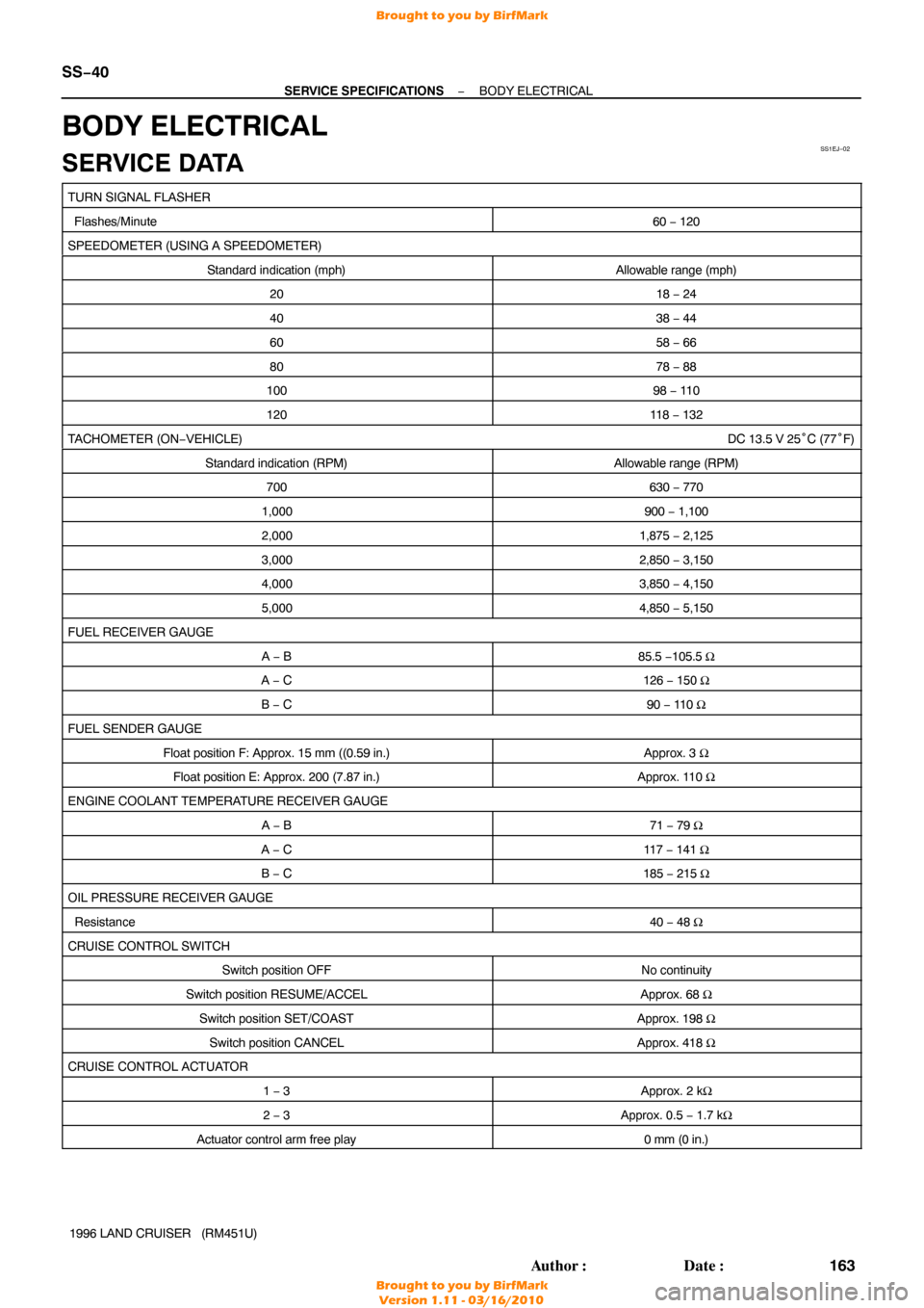
BODY ELECTRICAL
SERVICE DATA
TURN SIGNAL FLASHER
Flashes/Minute60 − 120
SPEEDOMETER (USING A SPEEDOMETER)
Standard indication (mph)Allowable range (mph)
2018 − 24
4038 − 44
6058 − 66
8078 − 88
10098 − 11 0
12011 8 − 132
TACHOMETER (ON− VEHICLE) DC 13.5 V 25°C (77° F)
Standard indication (RPM)Allowable range (RPM)
700630 − 770
1,000900 − 1,100
2,0001,875 − 2,125
3,0002,850 − 3,150
4,0003,850 − 4,150
5,0004,850 − 5,150
FUEL RECEIVER GAUGE
A − B85.5 − 105.5 Ω
A − C126 − 150 Ω
B − C90 − 110 Ω
FUEL SENDER GAUGE
Float position F: Approx. 15 mm ((0.59 in.)Approx. 3 Ω
Float position E: Approx. 200 (7.87 in.)Approx. 110 Ω
ENGINE COOLANT TEMPERATURE RECEIVER GAUGE
A − B71 − 79 Ω
A − C117 − 141 Ω
B − C185 − 215 Ω
OIL PRESSURE RECEIVER GAUGE
Resistance40 − 48 Ω
CRUISE CONTROL SWITCH
Switch position OFFNo continuity
Switch position RESUME/ACCELApprox. 68 Ω
Switch position SET/COASTApprox. 198 Ω
Switch position CANCELApprox. 418 Ω
CRUISE CONTROL ACTUATOR
1 − 3Approx. 2 kΩ
2 − 3Approx. 0.5 − 1.7 kΩ
Actuator control arm free play0 mm (0 in.)
Brought to you by BirfMark
Brought to you by BirfMark
Version 1.11 - 03/16/2010
Page 1344 of 1399
SS1EL−01
−
SERVICE SPECIFICATIONS AIR CONDITIONING
SS−43
166
Author�: Date�:
1996 LAND CRUISER (RM451U)
AIR CONDITIONING
SERVICE DATA
Refrigerant charge volume850 ± 50 g (59.98 ± 1.76 oz.)
Drive belt tension New belt
Used belt100 � 150 lbf
60 � 100 lbf
Idle− up speed800 rpm
Magnetic clutch clearance0.5 ± 0.15 mm (0.020 ± 0.0059 in.)
Brought to you by BirfMark
Brought to you by BirfMark
Version 1.11 - 03/16/2010
Page 1371 of 1399
TF0862
SST
TR0CN−01
TF0863
SST
TF0864
SST
SST
TR−10
−
TRANSFER TRANSFER ASSEMBLY
1996 LAND CRUISER (RM451U)
REPLACEMENT
1. REPLACE SHIFT LEVER OIL SEAL
(a) Using a screwdriver, pry out the oil seal.
(b) Using SST and a hammer, drive in a new oil seal. SST 0608−00081, 09950 −70010 (09951−07150)
2. REPLACE INPUT SHAFT OIL SEAL
(a) Using SST and a hammer, drive out the oil seal. SST 09316−60011 (09316 −00011)
(b) Using SST and a hammer, drive in a new oil seal. SST 09316−60011 (09316 −00011, 09316−00031)
Brought to you by BirfMark
Brought to you by BirfMark
Version 1.11 - 03/16/2010
Page 1381 of 1399
Q07113
SST
Q07114
SST
SST
Bearing
TR−20
−
TRANSFER CENTER DIFFERENTIAL
1996 LAND CRUISER (RM451U)
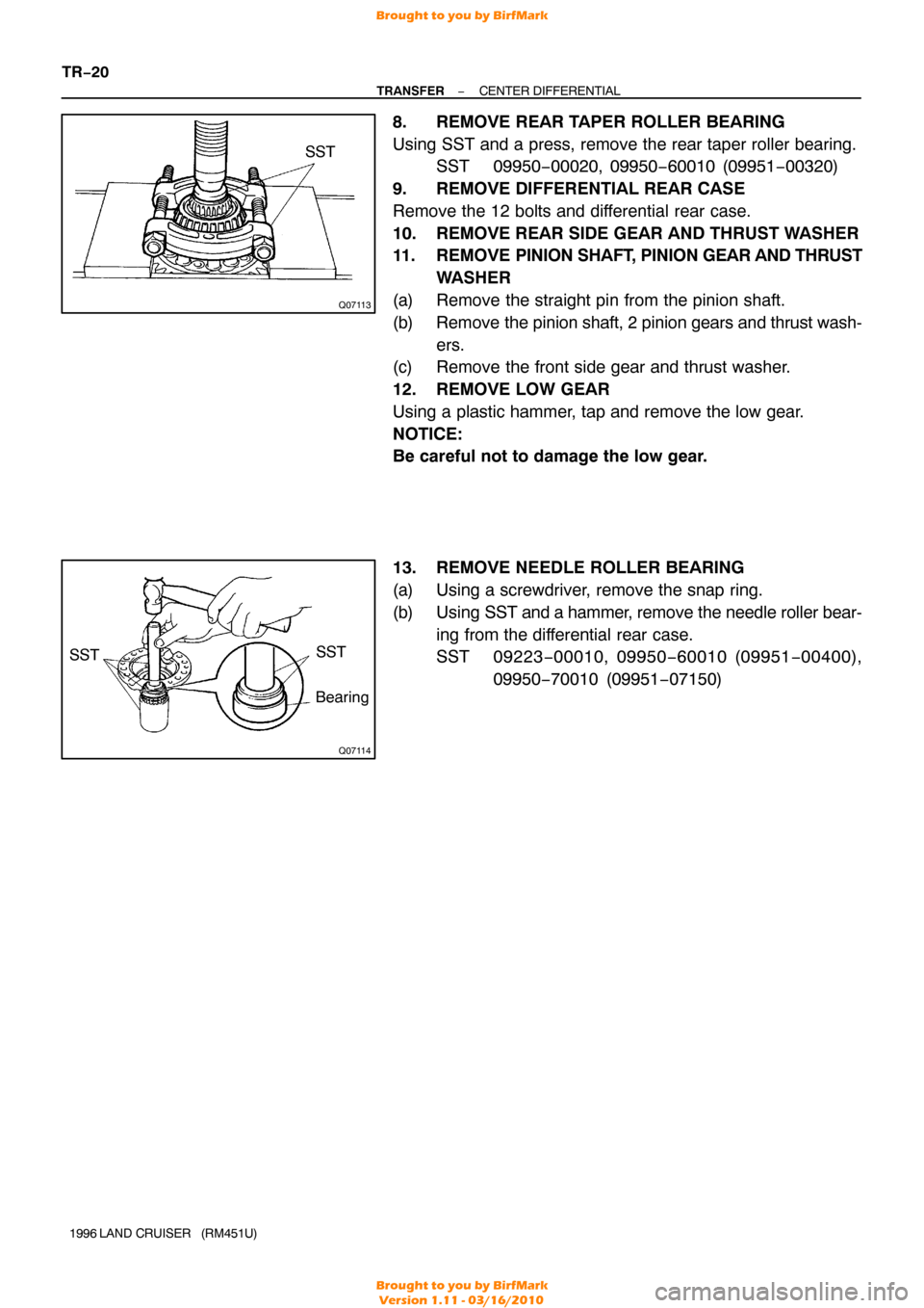
8. REMOVE REAR TAPER ROLLER BEARING
Using SST and a press, remove the rear taper roller bearing.
SST 09950−00020, 09950 −60010 (09951−00320)
9. REMOVE DIFFERENTIAL REAR CASE
Remove the 12 bolts and differential rear case.
10. REMOVE REAR SIDE GEAR AND THRUST WASHER
11. REMOVE PINION SHAFT, PINION GEAR AND THRUST
WASHER
(a) Remove the straight pin from the pinion shaft.
(b) Remove the pinion shaft, 2 pinion gears and thrust wash-
ers.
(c) Remove the front side gear and thrust washer.
12. REMOVE LOW GEAR
Using a plastic hammer, tap and remove the low gear.
NOTICE:
Be careful not to damage the low gear.
13. REMOVE NEEDLE ROLLER BEARING
(a) Using a screwdriver, remove the snap ring.
(b) Using SST and a hammer, remove the needle roller bear-
ing from the differential rear case.
SST 09223 −00010, 09950 −60010 (09951 −00400),
09950 −70010 (09951 −07150)
Brought to you by BirfMark
Brought to you by BirfMark
Version 1.11 - 03/16/2010
Page 1388 of 1399
TR0BG−01
TF0967
SST
TF0943
SST
TF0939
TF0945
SST
−
TRANSFER FRONT EXTENSION HOUSING
TR−27
1996 LAND CRUISER (RM451U)
REASSEMBLY
HINT:
Coat all of the sliding and rotating surfaces with gear oil before
assembly.
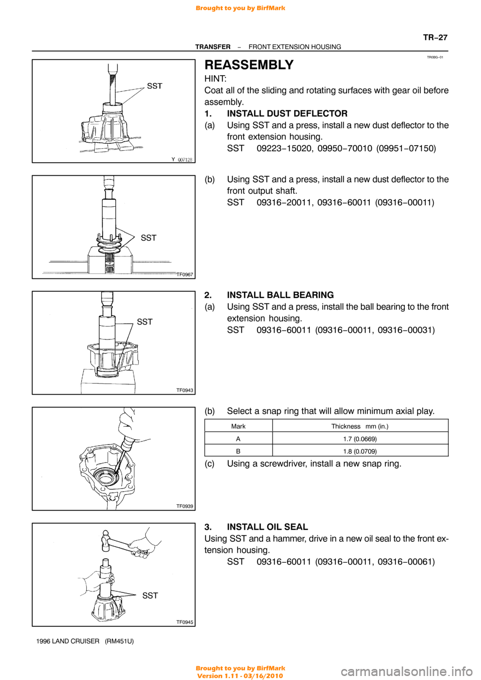
1. INSTALL DUST DEFLECTOR
(a) Using SST and a press, install a new dust deflector to the
front extension housing.
SST 09223−15020, 09950 −70010 (09951−07150)
(b) Using SST and a press, install a new dust deflector to the
front output shaft.
SST 09316−20011, 09316 −60011 (09316−00011)
2. INSTALL BALL BEARING
(a) Using SST and a press, install the ball bearing to the front
extension housing.
SST 09316−60011 (09316 −00011, 09316−00031)
(b) Select a snap ring that will allow minimum axial play.
MarkThickness mm (in.)
A1.7 (0.0669)
B1.8 (0.0709)
(c) Using a screwdriver, install a new snap ring.
3. INSTALL OIL SEAL
Using SST and a hammer, drive in a new oil seal to the front ex-
tension housing.
SST 09316−60011 (09316 −00011, 09316−00061)
Brought to you by BirfMark
Brought to you by BirfMark
Version 1.11 - 03/16/2010