Page 1217 of 1399
−
SFI INJECTOR
SF−31
1996 LAND CRUISER (RM451U)
(d) Remove SST.
SST 09268−41045
(e) Reinstall the fuel pressure regulator to the delivery pipe
(See page SF−22 ).
(f) Disconnect the TOYOTA hand− held tester from the
DLC3.
(g) Reinstall the fuse cover on the instrument panel.
Brought to you by BirfMark
Brought to you by BirfMark
Version 1.11 - 03/16/2010
Page 1219 of 1399
−
SFI INJECTOR
SF−33
1996 LAND CRUISER (RM451U)
(k) Connect the 6 injector connectors as shown.
2. INSTALL FUEL INLET PIPE
Install the fuel inlet pipe with 4 new gaskets, the 2 union bolts
and bolt.
Torque:
Union bolt: 29 N·m (300 kgf·cm, 22 ft·lbf)
Bolt: 20 N·m (200 kgf·cm, 14 ft·lbf)
3. INSTALL FUEL RETURN PIPE
(a) Install the fuel return pipe with the 2 bolts. Torque: 20 N·m (200 kgf·cm, 14 ft·lbf)
(b) Connect the fuel hose to the fuel pressure regulator.
4. INSTALL AIR INTAKE CHAMBER
Install 2 new gaskets and the air intake chamber with the 6 bolts
and 2 nuts. Torque: 21 N·m (210 kgf·cm, 15 ft·lbf)
5. CONNECT NO.1 WATER BYPASS HOSE TO CYL- INDER HEAD
6. CONNECT VACUUM HOSES TO TVV
Brought to you by BirfMark
Brought to you by BirfMark
Version 1.11 - 03/16/2010
Page 1245 of 1399
SF1F9−01
−
SFI VSV FOR FUEL PRESSURE CONTROL
SF−59
687
Author�: Date�:
1996 LAND CRUISER (RM451U)
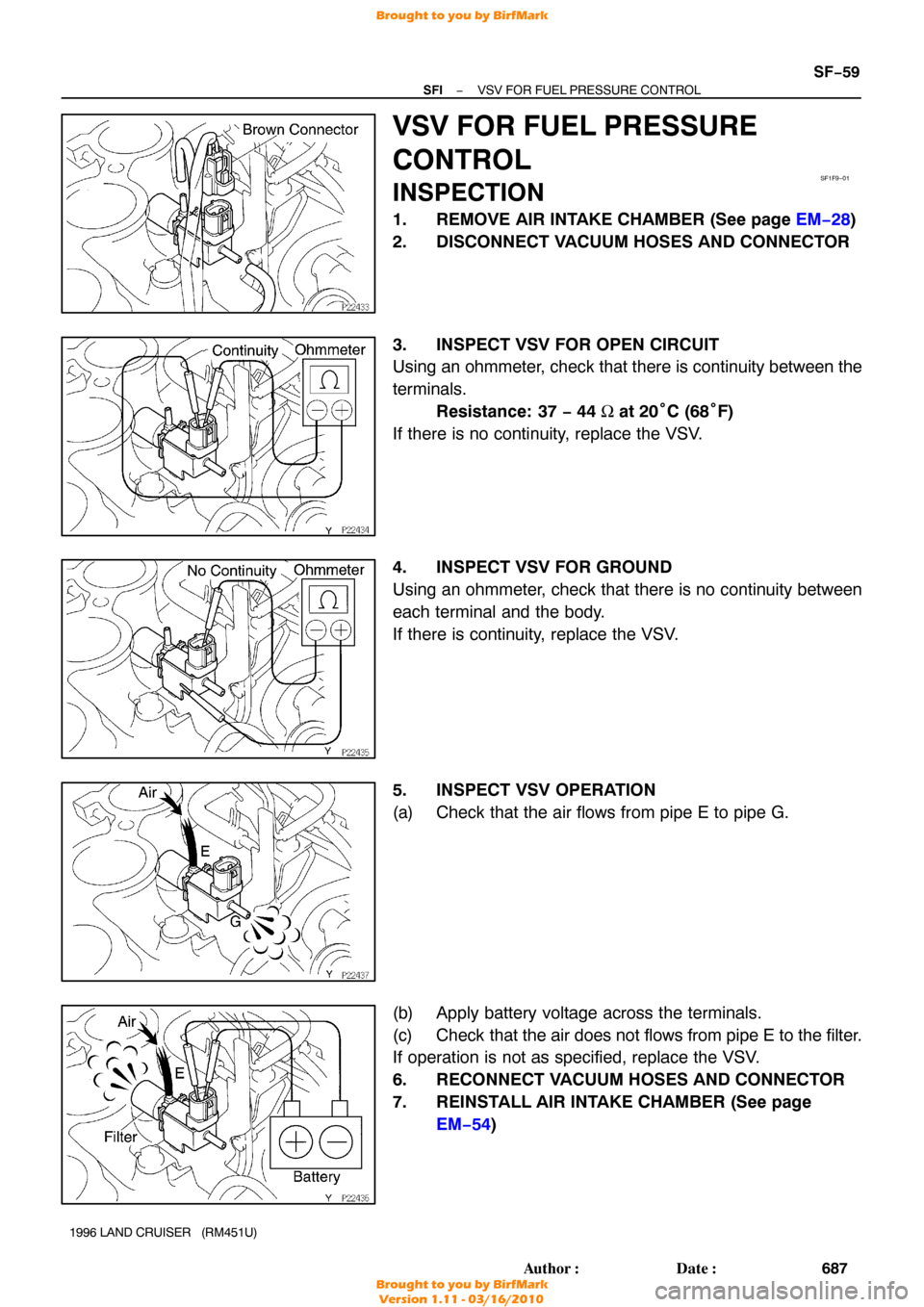
VSV FOR FUEL PRESSURE
CONTROL
INSPECTION
1. REMOVE AIR INTAKE CHAMBER (See page EM−28 )
2. DISCONNECT VACUUM HOSES AND CONNECTOR
3. INSPECT VSV FOR OPEN CIRCUIT
Using an ohmmeter, check that there is continuity between the
terminals. Resistance: 37 − 44 Ω at 20° C (68°F)
If there is no continuity, replace the VSV.
4. INSPECT VSV FOR GROUND
Using an ohmmeter, check that there is no continuity between
each terminal and the body.
If there is continuity, replace the VSV.
5. INSPECT VSV OPERATION
(a) Check that the air flows from pipe E to pipe G.
(b) Apply battery voltage across the terminals.
(c) Check that the air does not flows from pipe E to the filter.
If operation is not as specified, replace the VSV.
6. RECONNECT VACUUM HOSES AND CONNECTOR
7. REINSTALL AIR INTAKE CHAMBER (See page EM−54 )
Brought to you by BirfMark
Brought to you by BirfMark
Version 1.11 - 03/16/2010
Page 1312 of 1399

SFI
SERVICE DATA
Fuel pressure
regulatorFuel pressure at no vacuum265 − 304 kPa (2.7 − 3.1 kgf/c")
SS1ES−01
−
SERVICE SPECIFICATIONS SFI
SS−11
134
Author�: Date�:
1996 LAND CRUISER (RM451U)
SFI
SERVICE DATA
Fuel pressure
regulatorFuel pressure at no vacuum265 − 304 kPa (2.7 − 3.1 kgf/cm2, 38 − 44 psi)
Fuel pumpResistance at 20°C (68° F)0.2 − 3.0 Ω
InjectorResistance at 20°C (68° F)
Injection volume
Difference between each cylinder
Fuel leakage13.4 − 14.2 Ω
69 − 88 cm3 (4.2 − 5.4 cu in.) per 15 sec.
5 cm3 (0.3 cu in.) or less
1 drop or less per 12 min.
MAF meterResistance (THA − E2) at −20° C (− 4°F)
at 0° C (32° F)
at 20° C (68° F)
at 40° C (104° F)
at 60° C (140° F)
at 80° C (176° F)10 − 20 kΩ
4 − 7 kΩ
2 − 3 kΩ
0.9 − 1.3 kΩ
0.4 − 0.7 kΩ
0.2 − 0.4 kΩ
Throttle bodyThrottle body fully closed angle
Dashpot setting speed
Throttle opener setting speed6°
2,200 ± 300 rpm
700 − 1,000 rpm
Throttle position
sensorClearance between stop screw and lever
0 mm (0 in.) VTA − E2
0.50 mm (0.020 in.) IDL − E2
0.75 mm (0.030 in.) IDL − E2
Throttle valve fully open VTA − E2
− VC − E2
0.2 − 5.7 kΩ
2.3 kΩ or less
Infinity
2.0 − 10.2 kΩ
2.5 − 5.9 kΩ
IAC valveResistance (B1 − S1 and S3, B2 − S2 and S4)
at cold (− 10 − 50 ° C (−50 − 122° F))
at hot (50 − 100°C (122 − 212°F))
15 − 25 Ω
20 − 30 Ω
Fuel pump resistorResistance at 20°C (68° F)0.70 − 0.76 Ω
VSV for fuel pres-
sure controlResistance at 20°C (68° F)37 − 44 Ω
ECT sensorResistance at −20° C (− 4°F)
0 °C (32° F)
20 °C (68° F)
40 °C (104° F)
60 °C (140° F)
80 °C (176° F)10 − 20 kΩ
4 − 7 kΩ
2 − 3 kΩ
0.9 − 1.3 kΩ
0.4 − 0.7 kΩ
0.2 − 0.4 kΩ
EGR gas temp
sensorResistance at 50°C (122° F)
at 100° C (212° F)
150 °C (302° F)64 − 97 kΩ
11 − 16 kΩ
2 − 4 kΩ
Heated oxygen
sensorHeater coil resistance at 20°C (68° F)11 − 16 Ω
Fuel cut rpmFuel return rpm1,200 rpm
Brought to you by BirfMark
Brought to you by BirfMark
Version 1.11 - 03/16/2010
Page 1313 of 1399

TORQUE SPECIFICATION
Part tightenedN·mkgf·cmft·lbf
Fuel line for union bolt
for flare nut29
30300
31022
22
Second sea")
SS1ET−01
SS−12
−
SERVICE SPECIFICATIONS SFI
1996 LAND CRUISER (RM451U)
TORQUE SPECIFICATION
Part tightenedN·mkgf·cmft·lbf
Fuel line for union bolt
for flare nut29
30300
31022
22
Second seat x Body3940029
Fuel pump bracket assembly x Fuel tank3.94035 in.·lbf
Fuel inlet hose x Fuel filter2930022
Fuel inlet pipe x Fuel filter2930022
Fuel filter x Intake manifold2121015
Fuel pressure regulator x Delivery pipe2525018
Delivery pipe x Intake manifold2121015
Fuel inlet pipe x Delivery pipe Union bolt
Bolt29
20300
20022
14
Fuel inlet pipe x Fuel filter2930022
Fuel return pipe x Intake manifold2020014
Air intake chamber x Intake manifold2121015
Intake manifold stay x Air intake chamber3636026
Intake manifold stay x Cylinder block3636026
PS reservoir tank x Air intake chamber1818513
Heater inlet pipe x Air intake chamber2020014
Drain plug x Fuel tank6.56557 in.·lbf
Fuel tank breather tube x Fuel tank1.51513 in.·lbf
Fuel tank filler pipe x Fuel tank3.53531 in.·lbf
Fuel tank band x Body3940029
MAF meter x Bracket6.97061 in.·lbf
MAF meter x Air cleaner cap6.97061 in.·lbf
Throttle body x Air intake chamber2121015
Fuel pump resistor x Body1818513
ECT sensor x Cylinder head24.525017.5
EGR gas temperature sensor x Air intake chamber2020014
Knock sensor x Cylinder block4445033
Brought to you by BirfMark
Brought to you by BirfMark
Version 1.11 - 03/16/2010
Page 1341 of 1399

BODY ELECTRICAL
SERVICE DATA
TURN SIGNAL FLASHER
Flashes/Minute60 − 120
SPEEDOMETER")
SS1EJ−02
SS−40
−
SERVICE SPECIFICATIONS BODY ELECTRICAL
163
Author�: Date�:
1996 LAND CRUISER (RM451U)
BODY ELECTRICAL
SERVICE DATA
TURN SIGNAL FLASHER
Flashes/Minute60 − 120
SPEEDOMETER (USING A SPEEDOMETER)
Standard indication (mph)Allowable range (mph)
2018 − 24
4038 − 44
6058 − 66
8078 − 88
10098 − 11 0
12011 8 − 132
TACHOMETER (ON− VEHICLE) DC 13.5 V 25°C (77° F)
Standard indication (RPM)Allowable range (RPM)
700630 − 770
1,000900 − 1,100
2,0001,875 − 2,125
3,0002,850 − 3,150
4,0003,850 − 4,150
5,0004,850 − 5,150
FUEL RECEIVER GAUGE
A − B85.5 − 105.5 Ω
A − C126 − 150 Ω
B − C90 − 110 Ω
FUEL SENDER GAUGE
Float position F: Approx. 15 mm ((0.59 in.)Approx. 3 Ω
Float position E: Approx. 200 (7.87 in.)Approx. 110 Ω
ENGINE COOLANT TEMPERATURE RECEIVER GAUGE
A − B71 − 79 Ω
A − C117 − 141 Ω
B − C185 − 215 Ω
OIL PRESSURE RECEIVER GAUGE
Resistance40 − 48 Ω
CRUISE CONTROL SWITCH
Switch position OFFNo continuity
Switch position RESUME/ACCELApprox. 68 Ω
Switch position SET/COASTApprox. 198 Ω
Switch position CANCELApprox. 418 Ω
CRUISE CONTROL ACTUATOR
1 − 3Approx. 2 kΩ
2 − 3Approx. 0.5 − 1.7 kΩ
Actuator control arm free play0 mm (0 in.)
Brought to you by BirfMark
Brought to you by BirfMark
Version 1.11 - 03/16/2010

(d) Remove SST.
SST 09268−41045
(e) Reinstall the fuel pressure regulator to the delivery pipe
(See page SF−22 ).
(f) Disconnect the TOYOTA h")

(k) Connect the 6 injector connectors as shown.
2. INSTALL FUEL INLET PIPE
Install the fuel inlet pipe with 4 new gaskets, the 2 union bolts
and")