Page 1089 of 1399
W00531
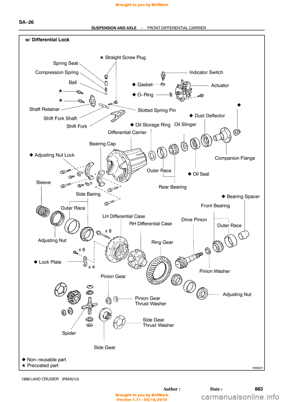
w/ Differential LockSide Gear
Thrust Washer
Pinion Gear
Thrust Washer
Outer Race
�
Oil Seal Companion Flange
Bearing Cap
Differential Carrier
� Adjusting Nut Lock Oil Slinger
Drive Pinion
Ring Gear
Side Baring
Adjusting Nut
�
Bearing Spacer
�
Oil Storage Ring
Outer Race
� Non− reusable part
�
Lock Plate x 8
x 4 �
O− Ring
Pinion Washer
Rear Bearing
�
� Dust Deflector
Front Bearing Outer Race
Adjusting Nut
Sleeve
Spider Side GearLH Differential Case
RH Differential Case
x 8
� Precoated part �
Gasket Indicator Switch
Actuator
�
Straight Screw Plug
Spring Seat
Compression Spring
Ball
�
Shaft Retainer Shift Fork Shaft Shift Fork
�
Slotted Spring Pin
Pinion Gear
SA−26
−
SUSPENSION AND AXLE FRONT DIFFERENTIAL CARRIER
883
Author�: Date�:
1996 LAND CRUISER (RM451U)
Brought to you by BirfMark
Brought to you by BirfMark
Version 1.11 - 03/16/2010
Page 1094 of 1399

11. REMOVE COMPANION FLANGE
(a) Using a chisel an")
SA2405
SST
R13141
SST
SA2402
SST
Z00641
SST
R13142
Matchmarks
−
SUSPENSION AND AXLE FRONT DIFFERENTIAL CARRIER
SA−31
1996 LAND CRUISER (RM451U)
11. REMOVE COMPANION FLANGE
(a) Using a chisel and hammer, unstake the nut.
(b) Using SST to hold the flange, remove the nut and plate
washer.
SST 09330−00021
(c) Using SST, remove the companion flange. SST 09950 −30010 (09951 −03010, 09953 −03010,
09954 −03010, 09955 −03030, 09956−03020)
12. REMOVE OIL SEAL AND OIL SLINGER
(a) Using SST, remove the oil seal from the dif ferential carrier.
SST 09308−10010
(b) Remove the oil slinger.
13. REMOVE REAR BEARING
Using SST, remove the rear bearing from the drive pinion. SST 09556−22010
14. REMOVE DIFFERENTIAL CASE
(a) Place matchmarks on the bearing cap and dif ferential car-
rier.
(b) Remove the 2 adjusting nut locks.
(c) Remove the 4 bolts and 2 bearing caps.
(d) w/o Differential lock: Remove the 2 adjusting nuts.
(e) w/o Differential lock: Remove the differential case with the side bearing outer
races from the carrier.
Brought to you by BirfMark
Brought to you by BirfMark
Version 1.11 - 03/16/2010
Page 1095 of 1399

HINT:
Tag the di")
FA2045
SST
SA2431
SST
Rear Bearing Outer Race
SA2410
Oil Strage Ring
Front Bearing
Outer Race
SA−32
−
SUSPENSION AND AXLE FRONT DIFFERENTIAL CARRIER
1996 LAND CRUISER (RM451U)
HINT:
Tag the disassembled parts to show the location for reassemb-
ly.
(f) w/ Differential lock:
Remove the differential case with the side bearing outer
race, adjusting nuts and sleeve from the differential carri-
er.
(g) w/ Differential lock: Remove the shift fork.
15. REMOVE DRIVE PINION AND BEARING SPACER
(a) Remove the drive pinion with the front bearing.
(b) Remove the bearing spacer.
16. REMOVE DRIVE PINION FRONT BEARING
(a) Using SST and a press, remove the bearing from the drive
pinion.
SST 09950−00020
HINT:
If the drive pinion or ring gear are damaged, replace them as
a set.
(b) Remove the plate washer from the drive pinion.
17. REMOVE FRONT AND REAR BEARING OUTER
RACES AND OIL STORAGE RING
(a) Using SST, remove the rear bearing outer race. SST 09308−00010
(b) Using a brass bar and hammer, remove the oil storage ring and front bearing outer race.
HINT:
Do not remove the oil storage ring unless replacing it with a new
one.
Brought to you by BirfMark
Brought to you by BirfMark
Version 1.11 - 03/16/2010
Page 1102 of 1399

7. CHECK RING GEAR RUNOUT
(a) Install the dif")
SA2465
SA2406
SST
SA2203
SSTSST
Front
Rear
FA2042
SST
R13140
SST
−
SUSPENSION AND AXLE FRONT DIFFERENTIAL CARRIER
SA−39
1996 LAND CRUISER (RM451U)
7. CHECK RING GEAR RUNOUT
(a) Install the differential case onto the carrier and tighten the
adjusting nut just to where there is no play in the bearings.
(b) Using a dial indicator, check the ring gear runout. Maximum runout: 0.10 mm (0.0039 in.)
(c) Remove the differential case.
8. INSTALL OIL STORAGE RING
Using SST and a hammer, install a new oil storage ring. SST 09316−60011 (09316 −00011, 09316−00021)
9. INSTALL DRIVE PINION FRONT AND REAR BEARING
OUTER RACES
�Front side:
Using SST and a press, install the 2 outer races.
SST 09316−60011 (09316 −00011, 09316−00051)
�Rear side:
Using SST and a press, install the 2 outer races.
SST 09316−60011 (09316 −00011, 09316−00021)
10. INSTALL DRIVE PINION FRONT BEARING
(a) Install the plate washer on the drive pinion with the cham-
fered end facing the pinion gear.
(b) Using SST and a press, install the front bearing onto the
drive pinion.
SST 09506−30012
11. TEMPORARILY ADJUST DRIVE PINION PRELOAD
(a) Install the drive pinion, rear bearing and oil slinger.
HINT:
Assemble the spacer and oil seal after adjusting the gear con-
tact pattern.
(b) Install the companion flange with SST. SST 09550 −30010 (09951 −03010, 09953 −03010,
09954 −03010, 09955 −03030, 09956−03020)
Brought to you by BirfMark
Brought to you by BirfMark
Version 1.11 - 03/16/2010
Page 1106 of 1399

If the teeth are not contacting properly, use the following chart
to")
FA2041
Washer
W00529
SA2407
SST
R13140
SST
−
SUSPENSION AND AXLE FRONT DIFFERENTIAL CARRIER
SA−43
1996 LAND CRUISER (RM451U)
If the teeth are not contacting properly, use the following chart
to select a proper washer for correction.
Washer thickness
Thickness mm (in.)Thickness mm (in.)
1.70 (0.0669)2.03 (0.0799)
1.73 (0.0681)2.06 (0.0811)
1.76 (0.0693)2.09 (0.0823)
1.79 (0.0705)2.12 (0.0835)
1.82 (0.0717)2.15 (0.0846)
1.85 (0.0728)2.18 (0.0858)
1.88 (0.0740)2.21 (0.0870)
1.91 (0.0752)2.24 (0.0882)
1.94 (0.0764)2.27 (0.0894)
1.97 (0.0776)2.30 (0.0906)
2.00 (0.0787)2.33 (0.0917)
18. REMOVE COMPANION FLANGE (See page SA−29)
19. REMOVE OIL SLINGER AND REAR BEARING
20. REMOVE REAR BEARING OUTER RACE AND OIL STORAGE RING (See page SA−29 )
21. INSTALL BEARING SPACER AND REAR BEARING
(a) Install a new bearing spacer on the shaft.
(b) Install a new oil storage ring and rear bearing outer race (See page SA−29 ).
(c) Install the rear bearing and oil slinger.
22. INSTALL OIL SEAL
(a) Using SST, install a new oil seal, as shown. SST 09214−76011
Oil seal drive in depth: 1.0 mm (0.039 in.)
(b) Apply MP grease to the oil seal lip.
23. INSTALL COMPANION FLANGE
(a) Install the companion flange with SST. SST 09550 −30010 (09951 −03010, 09953 −03010,
09954 −03010, 09955 −03030, 09956−03020)
Brought to you by BirfMark
Brought to you by BirfMark
Version 1.11 - 03/16/2010
Page 1130 of 1399
SA1V9−01
−
SUSPENSION AND AXLE REAR AXLE HUB
SA−67
1996 LAND CRUISER (RM451U)
REMOVAL
1. REMOVE REAR WHEEL
2. REMOVE REAR AXLE SHAFT (See page SA−63 )
3. REMOVE BRAKE CALIPER AND DISC (See page BR−34 )
4. DISCONNECT ABS SPEED SENSOR
Remove the bolt and disconnect the ABS speed sensor.
5. REMOVE REAR AXLE BEARING LOCK NUT
(a) Remove the 2 screws from the lock nut.
(b) Using SST, remove the lock nut. SST 09509−25011
6. REMOVE REAR AXLE HUB
(a) Pull out the axle hub, remove the lock nut plate and outer
bearing.
(b) Remove the axle hub.
Brought to you by BirfMark
Brought to you by BirfMark
Version 1.11 - 03/16/2010
Page 1131 of 1399

REPLACEMENT
1. REMOVE OIL SEAL AND INNER BEARING
(a) Using SST, rem")
SA1VA−01
R13157
Brass Bar
Positions
R13158
SST
R13159
SA−68
−
SUSPENSION AND AXLE REAR AXLE HUB
1996 LAND CRUISER (RM451U)
REPLACEMENT
1. REMOVE OIL SEAL AND INNER BEARING
(a) Using SST, remove the oil seal.
SST 09308−00010
(b) Remove the inner bearing from the hub.
2. REMOVE BEARING OUTER RACE
Using a brass bar and hammer, remove the bearing outer
races.
NOTICE:
Be careful not to damage the ABS speed sensor rotor.
3. INSTALL BEARING OUTER RACE
�Outside race:
Using SST and a press, install new bearing outer races.
SST 09950−60020 (09951 −00710),
09950 −70010 (09951 −07150)
�Inside race:
Using SST and a press, install new bearing outer races.
SST 09950−60020 (09951 −00810),
09950 −70010 (09951 −07150)
4. PACK BEARINGS WITH MP GREASE
(a) Place MP grease on the palm of your hand.
(b) Pack grease into the bearing until the grease ooze out from the other side.
(c) Do the same around the bearing circumference.
5. COAT INSIDE OF HUB WITH MP GREASE
6. INSTALL INNER BEARING AND OIL SEAL
(a) Place inner bearing into the hub.
(b) Using SST, install a new oil seal into the hub. SST 09223−15020, 09950 −70010 (09951−07150)
(c) Apply MP grease to the oil seal lip.
Brought to you by BirfMark
Brought to you by BirfMark
Version 1.11 - 03/16/2010
Page 1132 of 1399

INSTALLATION
1. INSTALL REAR AXLE HUB
(a) Clean the hub installation posi")
SA1VB−01
R08001
Lock Nut Mark
Axle Housing
Mark
−
SUSPENSION AND AXLE REAR AXLE HUB
SA−69
1996 LAND CRUISER (RM451U)
INSTALLATION
1. INSTALL REAR AXLE HUB
(a) Clean the hub installation position of the axle housing and
apply MP grease thinly.
(b) Place the axle hub to the axle housing.
NOTICE:
Be careful not to damage the oil seal.
(c) Install the outer bearing.
2. INSTALL LOCK NUT PLATE AND REAR AXLE BEAR- ING LOCK NUT
(a) Place the lock nut plate on the axle housing, making sure
the tongue lines up with the key groove.
(b) Temporarily install the lock nut.
3. INSTALL DISC
Install the disc to the rear axle hub and temporarily install the
2 hub nuts.
4. ADJUST PRELOAD
(a) Using SST, torque the bearing lock nut.SST 09509−25011
Torque: 59 N·m (600 kgf·cm, 43 ft·lbf)
(b) Make the bearing smooth by turning the hub several
times.
(c) Using the SST, retighten the bearing lock nut. Torque: 59 N·m (600 kgf·cm, 43 ft·lbf)
(d) Using the SST, loosen the nut until it can be turned by
hand.
(e) Using a spring tension gauge, check the preload and tighten the nut until the preload is within the specification.
Preload (at starting):
26−57 N (2.6−5.8 kgf, 5.7−12.8 lbf)
NOTICE:
Make sure that there is no contact with the parking brake
shoe.
(f) Align the mark on the bearing lock nut and tip of axle housing under the above preload range.
Brought to you by BirfMark
Brought to you by BirfMark
Version 1.11 - 03/16/2010

REMOVAL
1. REMOVE REAR WHEEL
2. REMOVE REAR AXLE SHAFT (See page SA−63 )
3. REMOVE BRAKE CALIPER AND DISC (See")