Page 1022 of 1399

Y
545.0 mm (21.457 in.)
X
Y Differential
Side
Z00755
PR0081
Q07338
−
PROPELLER SHAFT SPIDER BEARING
PR�")
Z04247
ColorDrit Mark
Bearing Cup
Drit Mark
Yoke
Q07142
Type A Type B X
610.0 mm (24.016 in.)
Y
545.0 mm (21.457 in.)
X
Y Differential
Side
Z00755
PR0081
Q07338
−
PROPELLER SHAFT SPIDER BEARING
PR−7
855
Author�: Date�:
1996 LAND CRUISER (RM451U)
5. SELECT SPIDER BEARING
Select the bearing according to whether or not there is a drill
mark on the yoke section.
YokeBearing (T ype A)Bearing (Type B)
w/ drill markw/ color mark (White)w/ color mark (Red)
No drill markNo color markNo color mark
HINT:
At time of the reassemble, there are 2 types of rear propeller
shafts, type A and type B. Referring to the illustration, measure
the distance between the welding points X and Y to identify
which of the 2 types is used for the vehicle.
6. INSTALL SPIDER BEARING
(a) Apply MP grease to a new spider and bearings.
NOTICE:
Be careful not to apply too much grease.
(b) Align the matchmarks on the yoke and flange.
(c) Fit the spider into the yoke.
(d) Using SST, install the bearings on the spider. SST 09332−25010
(e) Using SST, adjust both bearings so that the snap ring grooves are at maximum and equal widths.
Brought to you by BirfMark
Brought to you by BirfMark
Version 1.11 - 03/16/2010
Page 1023 of 1399

7. INSTALL SNAP RINGS
(a) Install 2 new snap rings of equal thickness which will allow
0 − 0")
PR0069
PR0031
PR−8
−
PROPELLER SHAFT SPIDER BEARING
856
Author�: Date�:
1996 LAND CRUISER (RM451U)
7. INSTALL SNAP RINGS
(a) Install 2 new snap rings of equal thickness which will allow
0 − 0.05 mm (0 − 0.0020 in.) axial play.
HINT:
Do not reuse the snap rings. Thickness of snap ring:
Front Propeller Shaft and Rear Propeller Shaft (Type
B)
ColorMarkThickness mm (in.)
−12.100 − 2.150
(0.0827 − 0.0846)
−22.150 − 2.200
(0.0846 − 0.0866)
−32.200 − 2.250
(0.0866 − 0.0886)
Brown−2.250 − 2.300
(0.0886 − 0.0906)
Blue−2.300 − 2.350
(0.0906 − 0.0925)
−62.350 − 2.400
(0.0925 − 0.0945)
−72.400 − 2.450
(0.0945 − 0.0965)
−82.450 − 2.500
(0.0965 − 0.0984)
Rear Propeller Shaft (Type A)
ColorThickness mm (in.)
−2.00 (0.0787)
Brown2.03 (0.0799)
Blue2.06 (0.0811)
−2.09 (0.0823)
(b) Using a hammer, tap the yoke until there is no clearance
between the bearing outer race and snap ring.
8. CHECK SPIDER BEARING (See page PR−4 )
�Check that the spider bearing moves smoothly.
�Check the spider bearing axial play.
Bearing axial play: Maximum 0.05 mm (0.0020 in.)
HINT:
�Install a new spider bearing on the flange side in the pro-
cedure described above.
�When replacing the spider bearing, be sure that the
grease fitting assembly hole is facing in the direction
shown in the illustration.
Brought to you by BirfMark
Brought to you by BirfMark
Version 1.11 - 03/16/2010
Page 1024 of 1399
Q09100
SPIDER GREASE FITTING ASSEMBLY DIRECTION
Front Propeller ShaftThe Figure at left shows the locations of
the grease fittings as seen from the rear.
Sleeve Yoke
No.1No.2
No.1
SPIDER GREASE FITTING ASSEMBLY DIRECTION
Rear Propeller Shaft Sleeve Yoke
Sleeve Yoke No.1
No.2
No.1
Sleeve Yoke The Figure at left shows the locations of
the grease fittings as seen from the
rear.
No.2
No.2
−
PROPELLER SHAFT SPIDER BEARING
PR−9
857
Author�: Date�:
1996 LAND CRUISER (RM451U)
Brought to you by BirfMark
Brought to you by BirfMark
Version 1.11 - 03/16/2010
Page 1064 of 1399

TROUBLESHOOTING
PROBLEM SYMPTOMS TABLE
Use the table below to help you find the cause of the")
SA1U7−01
−
SUSPENSION AND AXLE TROUBLESHOOTING
SA−1
858
Author�: Date�:
1996 LAND CRUISER (RM451U)
TROUBLESHOOTING
PROBLEM SYMPTOMS TABLE
Use the table below to help you find the cause of the problem. The numbers \
indicate the priority of the likely
cause of the problem. Check each part in order. If necessary, replace these parts.
(w/ Differential locking system):
�Check that center differential lock mode is set.
�When switching differential Free↔Lock, the indicator lamp will blink if the gears of the differen-
tial lock sleeve are not meshed. If this occurs, when the tires are rotated \
to apply differential
power to the differential, the differential locks and the indicator lamp\
light up.
SymptomSuspect AreaSee page
Wander/ pulls
1. Tires: worn or improperly inflated
2. Wheel alignmemt: incorrect
3. Steering linkage: loosen or worn
4. Hub bearings: loosen or worn
5. Steering gear: out of adjustment or brokenSA−3
SA−4
SR−47 SA−8
SR−41
Bottoming
1. Vehicle: overloaded
2. Spring weak
3. Shock absorber: worn out−
SA−49
SA−49
Sways/ pitches
1. Tires: worn or improperly inflated
2. Stabilizer bar: bent or broken
3. Shock absorber: worn outSA−3
SA−60
SA−49
Front wheel shimmy
1. Tires: worn or improperly inflated
2. Wheels: out of balance
3. Shock absorber: worn out
4. Wheel alignmemt: incorrect
5. Hub bearings: loosen or worn
6. Steering linkage: loosen or worn
7. Steering gear: out of adjustment or brokenSA−3
SA−3
SA−49 SA−3
SA−7
SR−45
SR−38
Abnormal tire wear
1. Tires: worn or improperly inflated
2. Wheel alignmemt: incorrect
3. Suspension parts: worn out
4. Shock absorber: worn outSA−3
SA−3 −
SA−49
Noise in front dif ferential
1. Oil level: low or wrong grade
2. Excessive backlash between pinion and ring gear
3. Ring, pinion ro side gears: worn or chipped
4. Pinion shaft bearing: worn
5. Side bearing: worn
6. Differential bearing: loosen or wornSA−21
SA−29
SA−29
SA−29
SA−29
SA−29
Oil leak from front dif ferential
1. Oil level: too high or wrong grade
2. Drive pinion oil seal: worn or damaged
3. Side gear oil seal: worn or damaged
4. Companion flange: loosen or damaged
5. Side gear shaft: damagedSA−21
SA−29
SA−29
SA−29
SA−29
Noise in rear axle
1. Oil level: low or wrong grade
2. Excessive backlash between pinion and ring gear
3. Ring, pinion ro side gears: worn or chipped
4. Pinion shaft bearing: worn
5. Axle shaft bearing: worn
6. Differential bearing: loosen or wornSA−73
SA−87
SA−87
SA−87
SA−87
SA−87
Oil leak from rear axle1. Oil seal: worn or damaged
2. Rear axle housing: crackedSA−73
−
Brought to you by BirfMark
Brought to you by BirfMark
Version 1.11 - 03/16/2010
Page 1066 of 1399

TIRE AND WHEEL
INSPECTION
1. INSPECT TIRE
(a) Check the tires for wear a")
SA1U8−02
R03031
R13503
R07928
−
SUSPENSION AND AXLE TIRE AND WHEEL
SA−3
860
Author�: Date�:
1996 LAND CRUISER (RM451U)
TIRE AND WHEEL
INSPECTION
1. INSPECT TIRE
(a) Check the tires for wear and for the proper inflation pres-
sure.
Cold tire inflation pressure: See page SS−30
(b) Check the tire runout. Tire runout: 3.0 mm (0.118 in.) or less
2. ROTATE TIRES
HINT:
See the illustration for where to rotate each tire.
3. INSPECT WHEEL BALANCE
(a) Check and adjust the Off−the−car balance.
(b) If necessary, check and adjust the On −the−car balance.
Unbalance after adjustment: 13.0 g (0.029 lb) or less
4. CHECK WHEEL BEARING LOOSENESS
Check the no backlash in the bearing shaft direction.
5. CHECK FRONT SUSPENSION FOR LOOSENESS
6. CHECK STEERING LINKAGE FOR LOOSENESS
7. CHECK BALL JOINT FOR LOOSENESS
8. CHECK SHOCK ABSORBER WORKS PROPERLY
�Check for oil leaks
�Check mounting bushings for wear
�Bounce front and rear of the vehicle
Brought to you by BirfMark
Brought to you by BirfMark
Version 1.11 - 03/16/2010
Page 1084 of 1399
SA1UK−01
Z15176
SST
R13186
SST
SA1973
SST
SA1969
SST
−
SUSPENSION AND AXLE FRONT DIFFERENTIAL REAR OIL SEAL
SA−21
1996 LAND CRUISER (RM451U)
REPLACEMENT
1. DRAIN DIFFERENTIAL OIL
2. REMOVE FRONT PROPELLER SHAFT
(See page PR−3 )
3. REMOVE COMPANION FLANGE
(a) Using a chisel and hammer, loosen the staked part of the
nut.
(b) Using SST to hold the flange, remove the nut and plate washer.
SST 09330−00021
(c) Using SST, remove the companion flange. SST 09950−30010 (09951 −03010, 09953−03010,
09954 −03010, 09955 −03030, 09956−03020)
4. REMOVE OIL SEAL AND OIL SLINGER
(a) Using SST, remove the oil seal. SST 09308−10010
(b) Remove the oil slinger.
5. REMOVE REAR BEARING
Using SST, remove the rear bearing from the drive pinion. SST 09556−22010
Brought to you by BirfMark
Brought to you by BirfMark
Version 1.11 - 03/16/2010
Page 1085 of 1399

R13139
SST
SA−22
−
SUSPENSION AND AXLE FRONT DIFFERENTIAL REAR OIL SEAL
1996 LAND CRUISER (RM451U)
6")
SA2430
SST
SA2271
R13155
SSTSST
Oil Storage Ring
Rear Bearing
SA2411
SST
1.0 mm (10.039 in.)
R13139
SST
SA−22
−
SUSPENSION AND AXLE FRONT DIFFERENTIAL REAR OIL SEAL
1996 LAND CRUISER (RM451U)
6. REMOVE REAR BEARING OUTER RACE
Using SST, remove the bearing outer race.
SST 09308−00010
NOTICE:
Do not scratch the taper surface of the outer race.
7. REMOVE OIL STORAGE RING
Using a screwdriver, bend the oil storage ring and drive it out.
8. REMOVE BEARING SPACER
9. INSTALL BEARING SPACER
10. INSTALL OIL STORAGE RING
Using SST, install a new oil storage ring. SST 09316−60011 (09316 −00011, 09316−00021)
11. INSTALL REAR BEARING
(a) Using SST, install the bearing outer race.
SST 09316−60011 (09316 −00011, 09316−00021)
(b) Install the rear bearing.
12. INSTALL OIL SLINGER AND OIL SEAL
(a) Install the oil slinger.
(b) Using SST, install a new oil seal, as shown. SST 09214−76011
Oil seal drive in depth: 1.0 mm (0.039 in.)
(c) Coat the lip of the oil seal with MP grease.
13. INSTALL COMPANION FLANGE
(a) Using SST, install the companion flange on the drive pin- ion.
SST 09950−30010 (09951 −03010, 09953−03010,
09954 −03010, 09955 −03030, 09956−03020)
(b) Place the plate washer on the companion flange.
Brought to you by BirfMark
Brought to you by BirfMark
Version 1.11 - 03/16/2010
Page 1088 of 1399
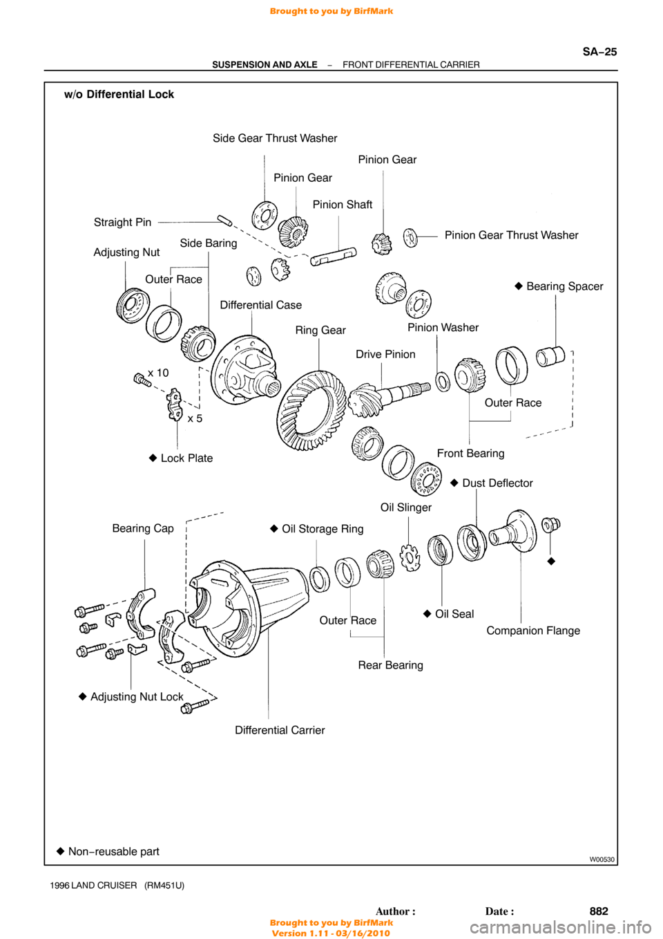
W00530
w/o Differential LockSide Gear Thrust WasherPinion Gear
Pinion Gear Thrust Washer
� Dust Deflector
Front Bearing Outer Race
� Oil Seal
Companion Flange
Bearing Cap
Differential Carrier
�
Adjusting Nut Lock Oil Slinger
Differential Case
Drive Pinion
Ring Gear
Side Baring
Straight Pin
Adjusting Nut
� Bearing Spacer
�
�
Oil Storage Ring
Outer Race
Outer Race
� Non− reusable part �
Lock Plate
x 10
x 5 Pinion Shaft
Pinion Gear
Pinion Washer
Rear Bearing
−
SUSPENSION AND AXLE FRONT DIFFERENTIAL CARRIER
SA−25
882
Author�: Date�:
1996 LAND CRUISER (RM451U)
Brought to you by BirfMark
Brought to you by BirfMark
Version 1.11 - 03/16/2010


REPLACEMENT
1. DRAIN DIFFERENTIAL OIL
2. REMOVE FRO")