Page 1334 of 1399

TORQUE SPECIFICATION
Part tightenedN·mkgf·cmft·lbf
FRONT
Axle hub x Disc6465047
Axle hub bearing lock")
SS1ED−02
−
SERVICE SPECIFICATIONS SUSPENSION AND AXLE
SS−33
1996 LAND CRUISER (RM451U)
TORQUE SPECIFICATION
Part tightenedN·mkgf·cmft·lbf
FRONT
Axle hub x Disc6465047
Axle hub bearing lock nut6465047
Flange x Axle hub3536026
Brake caliper x Axle carrier1231,25090
Brake caliper x Flexible hose3031022
Steering knuckle x Knuckle arm9698071
Bearing cap x Steering knuckle9698071
Knuckle arm x Tie rod9192567
Steering knuckle x Knuckle spindle4747534
Oil seal end retainer x Knuckle arm5.45548 in.·lbf
ABS speed sensor set bolt x Steering knuckle1818513
Hub nut Steel wheel
Aluminum wheel147
1031,500
1,050109 76
Drain plug4950036
Filler plug4950036
Propeller shaft x Companion flange8890065
Side bearing cap x Differential carrier7880058
Ring gear x Differential case9798571
Drive pinion x Companion flange196 − 3432,000 − 3,500145 − 253
Differential LH case x RH case4748035
Differential lock shift retainer2424017
Differential lock screw plug2222016
Differential lock indicator switch4041030
Differential lock actuator2627020
Differential carrier x Axle housing2728020
Adjusting nut lock x Bearing cap131309
Follow spring x Frame9.29482 in.·lbf
Stabilizer bar x Axle housing2526019
Shock absorber x Axle housing6970051
Shock absorber x Frame6970051
Stabilizer bar link x Cover1818513
Stabilizer bar link x Link bracket1031,05076
Lateral control rod x Frame1711,750127
Lateral control rod x Axle housing1711,750127
Leading arm x Frame1771,800130
Leading arm x Axle housing1711,750127
REAR
Rear axle shaft x Axle hub3434025
Rear axle bearing lock nut5960043
Rear axle bearing lock nut screw5.45548 in.·lbf
Brke caliper x Axle carrier1031,05076
ABS speed sensor set bolt1818513
Brought to you by BirfMark
Brought to you by BirfMark
Version 1.11 - 03/16/2010
Page 1335 of 1399

Hub nut
Steel wheel
Aluminum wheel
147
1031,500
1,050109 76
Drain plug4950036
Filler plug4950036
Pinion shaft pin w/")
SS−34
−
SERVICE SPECIFICATIONS SUSPENSION AND AXLE
1996 LAND CRUISER (RM451U)
Hub nut
Steel wheel
Aluminum wheel
147
1031,500
1,050109 76
Drain plug4950036
Filler plug4950036
Pinion shaft pin w/o Differential lock
w/ Differential lock27
58275
59020
43
Propeller shaft x Companion flange7475054
Side bearing cap x Differential carrier w/o Differential lock
w/ Differential lock78
11 3800
1,15058
83
Ring gear x Differential case11 01,12581
Companion flange x Drive pinion (Maximum torque)4414,500325
Differential carrier x Axle housing7374054
Adjusting nut lock x Bearing cap131309
Differential case x Differential cover5859043
Differential lock shift fork set bolt2020014
Differential lock actuator2424017
Differential lock cover1818513
Differential lock indicator switch4041030
Actuator protector Nut
Bolt35
20360
20026
14
Follow spring x Frame2829021
Shock absorber x Bracket6970051
Shock absorber bracket x Frame5051037
Shock absorber x Axle housing6465047
Lateral control rod x Frame1771,800130
Lateral control rod x Axle housing2452,500181
Upper control rod x Frame1771,800130
Upper control rod x Axle housing1771,800130
Lower control arm x Frame1771,800130
Lower control arm x Axle housing1771,800130
Stabilizer bar x Link2526019
Stabilizer bar link x Link bracket1031,05076
Cover x Axle housing1818513
Brought to you by BirfMark
Brought to you by BirfMark
Version 1.11 - 03/16/2010
Page 1339 of 1399

TORQUE SPECIFICATION
Part tightenedN·mkgf·cmft·lbf
TILT STEERING COLUMN
Steering wheel set nut3435025
Steeri")
SS1EH−02
SS−38
−
SERVICE SPECIFICATIONS STEERING
1996 LAND CRUISER (RM451U)
TORQUE SPECIFICATION
Part tightenedN·mkgf·cmft·lbf
TILT STEERING COLUMN
Steering wheel set nut3435025
Steering wheel pad set screw (T orx screw)9.09078 in.·lbf
Steering column assembly set nut and bolt2525018
Sliding yoke sub−assembly x Worm gear valve body shaft3435025
Sliding yoke sub −assembly x Intermediate No. 2 shaft3435025
Universal joint x Intermediate No. 2 shaft3435025
Main shaft assembly x Universal joint3435025
Turn signal bracket set bolt4.95043 in.·lbf
Tilt sub lever side pawl set bolt x Nut5.96052 in.·lbf
Tilt lever retainer set nut1515011
Tilt lever assembly set bolt2.93026 in.·lbf
Compression spring set bolt7.88069 in.·lbf
Column hole cover x Lower dust seal5.96052 in.·lbf
Column hole cover x Body131309
Link joint protector set bolt121209
PS VANE PUMP
Pressure feed tube set union bolt5657542
PS vane pump assembly set nut3637027
Suction port union set bolt131309
Vane pump drive gear set nut7475054
Pressure port union6970051
PS GEAR
Pressure tube x Gear housing assembly for use with SST
for use without SST36
44365
45026
33
Return tube x Gear housing assembly for use with SST
for use without SST36
44365
45026
33
Gear housing assembly x Body1421,450105
Pitman arm x Cross shaft1771,800130
Cross shaft adjusting screw set nut4647034
Side cover x Gear housing6162045
Plunger guide nut2020515
Worm gear valve body assembly x Gear housing6162045
Control valve shaft x Sliding york sub −assembly3435025
STEERING LINKAGE
Pitman arm x Cross shaft1771,800130
Pitman arm x Relay rod9192567
Tie rod clamp bolt3737527
Tie rod x Knuckle arm9192567
Relay rod x Steering damper7475054
Steering damper x Steering damper bracket7475054
Steering damper bracket x Body7475054
Relay rod clamp bolt3737527
Brought to you by BirfMark
Brought to you by BirfMark
Version 1.11 - 03/16/2010
Page 1344 of 1399
SS1EL−01
−
SERVICE SPECIFICATIONS AIR CONDITIONING
SS−43
166
Author�: Date�:
1996 LAND CRUISER (RM451U)
AIR CONDITIONING
SERVICE DATA
Refrigerant charge volume850 ± 50 g (59.98 ± 1.76 oz.)
Drive belt tension New belt
Used belt100 � 150 lbf
60 � 100 lbf
Idle− up speed800 rpm
Magnetic clutch clearance0.5 ± 0.15 mm (0.020 ± 0.0059 in.)
Brought to you by BirfMark
Brought to you by BirfMark
Version 1.11 - 03/16/2010
Page 1351 of 1399
P04683(1) (5)(4)
(2)
(3)
P04515
Magnetic Finger
P23004
P04525
ST−6
−
STARTING STARTER
1996 LAND CRUISER (RM451U)
(b) Remove these parts from the magnetic switch assembly:
(1) Starter housing
(2) Return spring
(3) Bearing
(4) Idler gear
(5) Starter clutch assembly
3. REMOVE STEEL BALL
Using a magnetic finger, remove the steel ball from the clutch
shaft hole.
4. REMOVE BRUSH HOLDER
(a) Remove the 2 screws, 2 O −rings and end cover from the
field frame.
Torque:
1.4 kW type: 1.5 N·m (15 kgf·cm, 13 in.·lbf)
2.0 kW type: 3.8 N·m (40 kgf·cm, 35 in.·lbf)
HINT:
At the time of reassembly, use new O−rings.
(b) Remove the O−ring from the field frame.
HINT:
At the time of reassembly, use a new O−ring.
(c) Using a screwdriver, hold the spring back and disconnect
the brush from the brush holder. Disconnect the four
brushes and remove the brush holder.
5. REMOVE ARMATURE FROM FIELD FRAME
Brought to you by BirfMark
Brought to you by BirfMark
Version 1.11 - 03/16/2010
Page 1354 of 1399

Minimum spring installed load:
1.4 kW type: 11.8 N (1.20 kgf, 2.7 lbf)
2.0 kW type: 12.7 N (1.29")
P21088
OhmmeterNo Continuity
P10821
Lock
Free
−
STARTING STARTER
ST−9
1996 LAND CRUISER (RM451U)
Minimum spring installed load:
1.4 kW type: 11.8 N (1.20 kgf, 2.7 lbf)
2.0 kW type: 12.7 N (1.29 kgf, 2.9 lbf)
If the installed load is less than minimum replace the brush
springs.
11. INSPECT BRUSH HOLDER INSULATION
Using an ohmmeter, check that there is no continuity between
the positive (+) and negative ( −) brush holders.
If there is continuity, repair or replace the brush holder.
12. INSPECT GEAR TEETH
Check the gear teeth on the pinion gear, idler gear and clutch
assembly for wear or damage.
If damaged, replace the gear or clutch assembly.
If damaged, also check the drive plate ring gear for wear or
damage.
13. INSPECT CLUTCH PINION GEAR
Hold the starter clutch and rotate the pinion gear clockwise, and
check that it turns freely. Try to rotate the pinion gear counter-
clockwise and check that it locks.
If necessary, replace the clutch assembly.
14. INSPECT REAR BEARING
Turn each bearing by hand while applying inward force.
If resistance is felt or the bearing sticks, replace the bearing.
15. INSPECT FRONT BEARING
Turn each bearing by hand while applying inward force.
If resistance is felt or the bearing sticks, replace the bearing.
Brought to you by BirfMark
Brought to you by BirfMark
Version 1.11 - 03/16/2010
Page 1364 of 1399
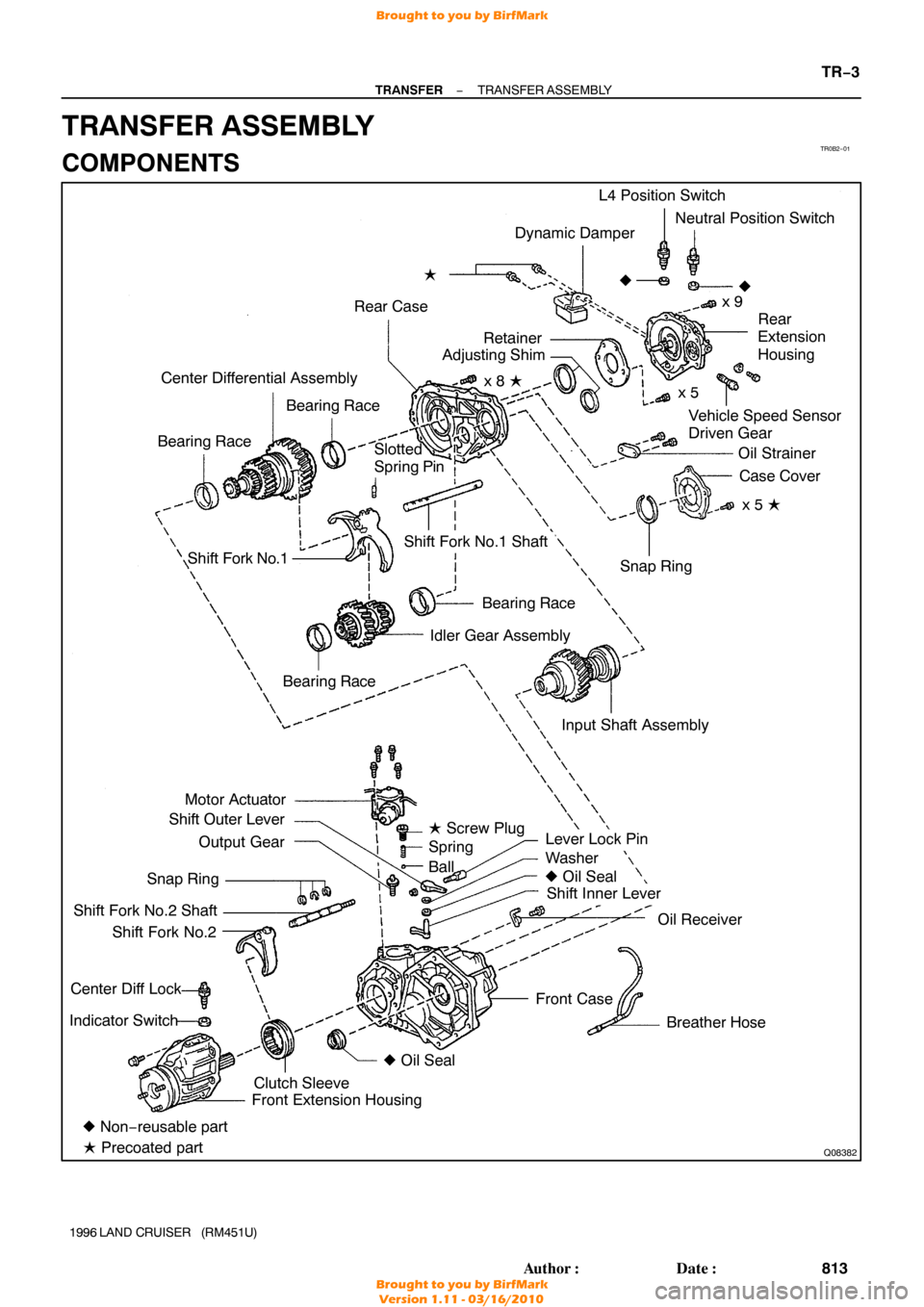
TR0B2−01
Q08382
Dynamic Damper
Rear Case �
Vehicle Speed Sensor
Driven Gear
Center Differential Assembly
Bearing Race
Bearing Race L4 Position Switch
Neutral Position Switch
x 9
�
Rear
Extension
Housing
Oil Strainer Case Cover
x 5 �
Shift Fork No.1
Bearing Race
Idler Gear Assembly
Motor Actuator
Shift Outer Lever
Output Gear
Snap Ring
Shift Fork No.2 Shaft Shift Fork No.2
Center Diff Lock
Indicator Switch
Lever Lock Pin
Washer
� Oil Seal
Shift Inner Lever
Oil Receiver
Breather Hose
Front Case Snap Ring
Shift Fork No.1 Shaft
� Non− reusable part
� Precoated part Front Extension Housing
Clutch Sleeve �
Oil Seal
Bearing Race
�
Slotted
Spring Pin
Input Shaft Assemblyx 5
x 8 �
Retainer
Adjusting Shim
� Screw Plug
Spring
Ball
−
TRANSFER TRANSFER ASSEMBLY
TR−3
813
Author�: Date�:
1996 LAND CRUISER (RM451U)
TRANSFER ASSEMBLY
COMPONENTS
Brought to you by BirfMark
Brought to you by BirfMark
Version 1.11 - 03/16/2010
Page 1366 of 1399

6. REMOVE TRANSFER INDICATOR SWITCH
Remove the Center Diff Lock indicator switch, L4 position")
Q04610
Q00541
Front
Q02950
Q07125
FIPG
−
TRANSFER TRANSFER ASSEMBLY
TR−5
1996 LAND CRUISER (RM451U)
6. REMOVE TRANSFER INDICATOR SWITCH
Remove the Center Diff Lock indicator switch, L4 position
switch, Neutral position switch and 3 gaskets.
Torque: 37 N·m (380 kgf·cm, 27 ft·lbf)
7. REMOVE FRONT EXTENSION HOUSING
Remove the 6 bolts and front extension housing.
HINT:
If necessary, tap the front extension housing with a plastic ham-
mer.
HINT:
At the time of reassembly, please refer to the following items.
�Set the clutch sleeve in differential lock condition.
�Apply FIPG to the front case.
FIPG: Part No. 08826−00090, THREE BOND 1281 or
equivalent
Torque: 37 N·m (380 kgf·cm, 27 ft·lbf)
8. REMOVE CLUTCH SLEEVE, SHIFT FORK NO.2 SHAFT AND SHIFT FORK NO.2
HINT:
At the time of reassebly, make sure to install the clutch sleeve
in the correct direction.
9. SEPARATE SHIFT FORK NO.2 SHAFT AND SHIFT FORK NO.2
(a) Using 2 screwdrivers and a hammer, tap out the 3 snap rings from the shift fork No.2 shaft.
(b) Separate the shift fork No.2 shaft and shift fork No.2.
10. REMOVE REAR EXTENSION HOUSING
Remove the 9 bolts and rear extension housing.
HINT:
If necessary, tap the rear extension housing with a plastic ham-
mer.
HINT:
At the time of reassembly, apply FIPG to the rear case. FIPG: Part No. 08826−00090, THREE BOND 1281 or
equivalent
Torque: 37 N·m (380 kgf·cm, 27 ft·lbf)
Brought to you by BirfMark
Brought to you by BirfMark
Version 1.11 - 03/16/2010

 (5)(4)
(2)
(3)
P04515
Magnetic Finger
P23004
P04525
ST−6
−
STARTING STARTER
1996 LAND CRUISER (RM451U)
(b) Remove these parts from the magnetic switch assembly:
(1) Starter housing
(2")