Page 1159 of 1399
FA2013
Proper ContactHeel Contact
Face Contact
Select an adjusting washer that will bring the drive
pinion closer to the ring gear.
Select an adjusting washer that will shift the drive
pinion away from the ring gear.
Toe Contact
Flank Contact
FA2041
Washer
SA2394
SA−96
−
SUSPENSION AND AXLE REAR DIFFERENTIAL CARRIER
1996 LAND CRUISER (RM451U)
If the teeth are not contacting properly, use the following chart
to select a proper washer for correction.
Thickness mm (in.)Thickness mm (in.)
1.05 (0.0413)1.35 (0.0531)
1.10 (0.0433)1.40 (0.0551)
1.15 (0.0453)1.45 (0.0571)
1.20 (0.0472)1.50 (0.0591)
1.25 (0.0492)1.55 (0.0610)
1.30 (0.0512)−
19. REMOVE COMPANION FLANGE (See page SA−29)
20. REMOVE OIL SLINGER AND FRONT BEARING (See
page SA−29 )
21. INSTALL BEARING SPACER AND FRONT BEARING
(a) Install a new bearing spacer on the shaft.
(b) Install the front bearing and oil slinger.
Brought to you by BirfMark
Brought to you by BirfMark
Version 1.11 - 03/16/2010
Page 1160 of 1399

SA2454
SST
R13414
SST
SA2351
SST
SA2446
−
SUSPENSION AND AXLE REAR DIFFERENTIAL CARRIER
SA−97
1996 LAND CRUISER (RM451U)
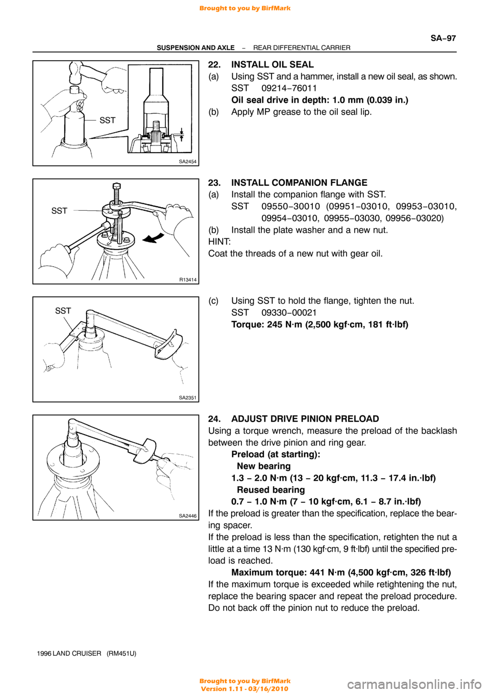
22. INSTALL OIL SEAL
(a) Using SST and a hammer, install a new oil seal, as shown.
SST 09214−76011
Oil seal drive in depth: 1.0 mm (0.039 in.)
(b) Apply MP grease to the oil seal lip.
23. INSTALL COMPANION FLANGE
(a) Install the companion flange with SST. SST 09550 −30010 (09951 −03010, 09953 −03010,
09954 −03010, 09955 −03030, 09956−03020)
(b) Install the plate washer and a new nut.
HINT:
Coat the threads of a new nut with gear oil.
(c) Using SST to hold the flange, tighten the nut. SST 09330−00021
Torque: 245 N·m (2,500 kgf·cm, 181 ft·lbf)
24. ADJUST DRIVE PINION PRELOAD
Using a torque wrench, measure the preload of the backlash
between the drive pinion and ring gear. Preload (at starting):
New bearing
1.3 − 2.0 N·m (13 − 20 kgf·cm, 11.3 − 17.4 in.·lbf)
Reused bearing
0.7 − 1.0 N·m (7 − 10 kgf·cm, 6.1 − 8.7 in.·lbf)
If the preload is greater than the specification, replace the bear-
ing spacer.
If the preload is less than the specification, retighten the nut a
little at a time 13 N·m (130 kgf·cm, 9 ft·lbf) until the specified pre-
load is reached. Maximum torque: 441 N·m (4,500 kgf·cm, 326 ft·lbf)
If the maximum torque is exceeded while retightening the nut,
replace the bearing spacer and repeat the preload procedure.
Do not back off the pinion nut to reduce the preload.
Brought to you by BirfMark
Brought to you by BirfMark
Version 1.11 - 03/16/2010
Page 1161 of 1399

Z15220
FIPG Width Approx.
1 − 2 mm (0.04 − 0.08 in.)
SA2129
Z10150
Adhesive
SA−98
−
SUSPENSION AND AXLE REAR DIFFERENTIAL CARRIER
1996 LAND CRUISER (RM451U)
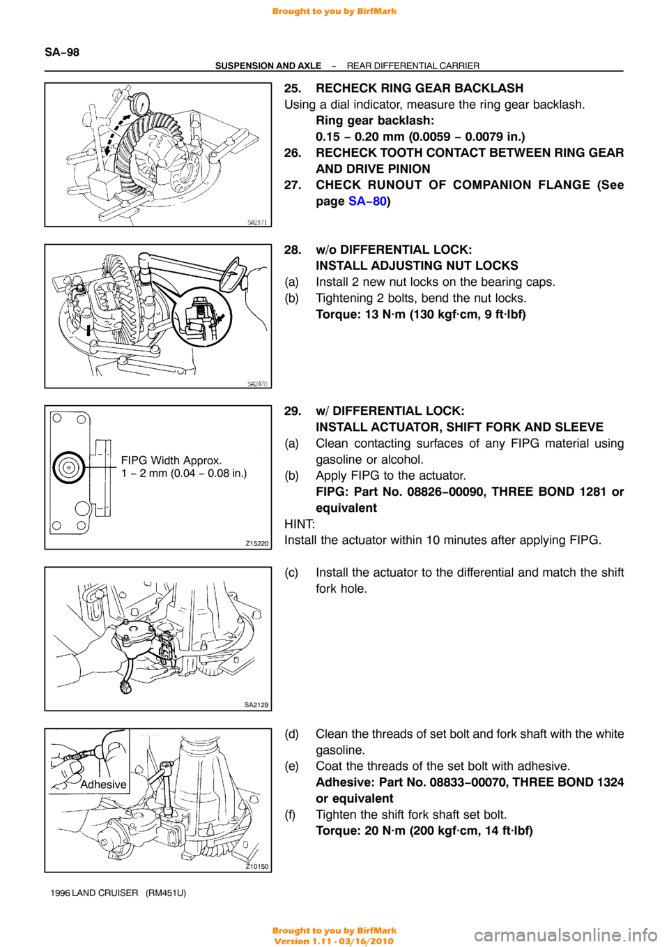
25. RECHECK RING GEAR BACKLASH
Using a dial indicator, measure the ring gear backlash.
Ring gear backlash:
0.15 − 0.20 mm (0.0059 − 0.0079 in.)
26. RECHECK TOOTH CONTACT BETWEEN RING GEAR AND DRIVE PINION
27. CHECK RUNOUT OF COMPANION FLANGE (See
page SA−80 )
28. w/o DIFFERENTIAL LOCK: INSTALL ADJUSTING NUT LOCKS
(a) Install 2 new nut locks on the bearing caps.
(b) Tightening 2 bolts, bend the nut locks. Torque: 13 N·m (130 kgf·cm, 9 ft·lbf)
29. w/ DIFFERENTIAL LOCK: INSTALL ACTUATOR, SHIFT FORK AND SLEEVE
(a) Clean contacting surfaces of any FIPG material using gasoline or alcohol.
(b) Apply FIPG to the actuator.
FIPG: Part No. 08826−00090, THREE BOND 1281 or
equivalent
HINT:
Install the actuator within 10 minutes after applying FIPG.
(c) Install the actuator to the differential and match the shift fork hole.
(d) Clean the threads of set bolt and fork shaft with the white
gasoline.
(e) Coat the threads of the set bolt with adhesive.
Adhesive: Part No. 08833 −00070, THREE BOND 1324
or equivalent
(f) Tighten the shift fork shaft set bolt. Torque: 20 N·m (200 kgf·cm, 14 ft·lbf)
Brought to you by BirfMark
Brought to you by BirfMark
Version 1.11 - 03/16/2010
Page 1171 of 1399
SA2621
SA−108
−
SUSPENSION AND AXLE DIFFERENTIAL LOCKING SYSTEM
1996 LAND CRUISER (RM451U)
(f) Remove the shift fork set bolt.
(g) Remove the 4 bolts.
(h) Using a screwdriver, pry out the actuator.
Brought to you by BirfMark
Brought to you by BirfMark
Version 1.11 - 03/16/2010
Page 1198 of 1399
SF1EI−03
−
SFI FUEL PUMP
SF−13
1996 LAND CRUISER (RM451U)
DISASSEMBLY
1. REMOVE FUEL PUMP FROM FUEL PUMP BRACKET
(a) Pull off the lower side of the fuel pump from the pump
bracket.
(b) Disconnect the fuel pump connector.
(c) Disconnect the fuel hose from the fuel pump, and remove
the fuel pump.
(d) Remove the rubber cushion from the fuel pump.
2. REMOVE FUEL PUMP FILTER FROM FUEL PUMP
(a) Using a small screwdriver, remove the clip.
HINT:
At the time of installation, plaese refer to the following items.
install the pump filter with a new clip.
(b) Pull out the pump filter.
3. REMOVE FUEL SENDER GAUGE FROM FUEL PUMP BRACKET
(a) Remove the 3 screws and disconnect the lead wires from
the pump bracket.
(b) Remove the 2 screws and sender gauge.
Brought to you by BirfMark
Brought to you by BirfMark
Version 1.11 - 03/16/2010
Page 1254 of 1399
SR164−01
−
STEERING STEERING SYSTEM
SR−1
1052
Author�: Date�:
1996 LAND CRUISER (RM451U)
STEERING SYSTEM
PRECAUTION
�Care must be taken to replace parts properly because they could affect the pe\
rformance
of the steering system and result in a driving hazard.
�The LAND CRUISER is equipped with SRS (Supplemental Restraint System) suc\
h as the
driver airbag and front passenger airbag. Failure to carry out service o\
peration in the
correct sequence could cause the SRS to unexpectedly deploy during servicing, possi-
bly leading to a serious accident. Before servicing (including removal or \
installation of
parts, inspection or replacement), be sure to read the precautionary notices \
in the RS
section.
Brought to you by BirfMark
Brought to you by BirfMark
Version 1.11 - 03/16/2010
Page 1266 of 1399

SR16C−01
−
STEERING TILT STEERING COLUMN
SR−15
1996 LAND CRUISER (RM451U)
INSPECTION
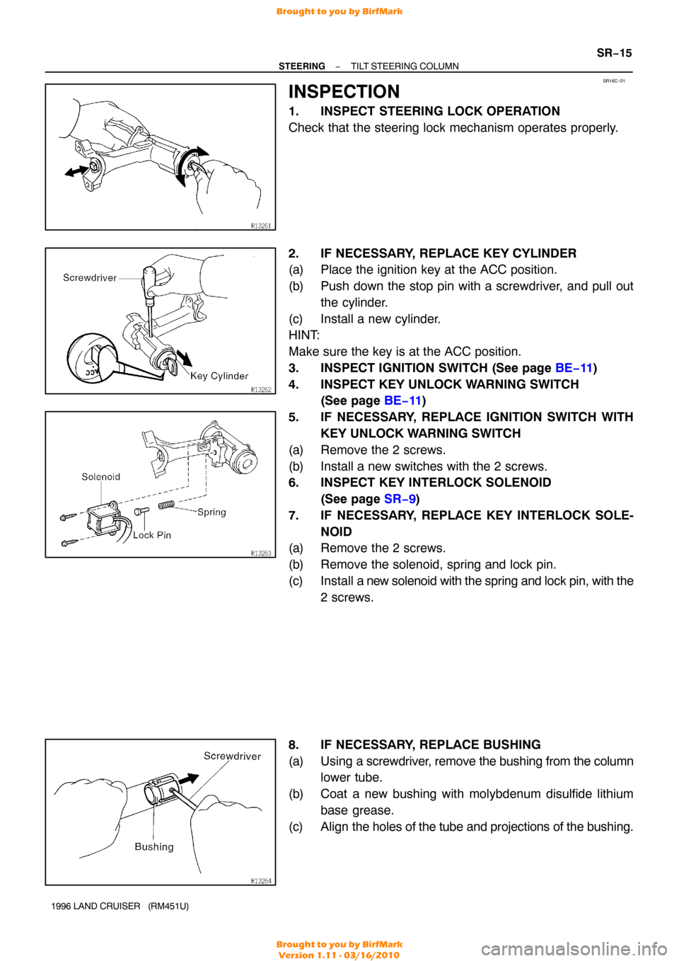
1. INSPECT STEERING LOCK OPERATION
Check that the steering lock mechanism operates properly.
2. IF NECESSARY, REPLACE KEY CYLINDER
(a) Place the ignition key at the ACC position.
(b) Push down the stop pin with a screwdriver, and pull out
the cylinder.
(c) Install a new cylinder.
HINT:
Make sure the key is at the ACC position.
3. INSPECT IGNITION SWITCH (See page BE−11)
4. INSPECT KEY UNLOCK WARNING SWITCH (See page BE−11 )
5. IF NECESSARY, REPLACE IGNITION SWITCH WITH KEY UNLOCK WARNING SWITCH
(a) Remove the 2 screws.
(b) Install a new switches with the 2 screws.
6. INSPECT KEY INTERLOCK SOLENOID (See page SR−9 )
7. IF NECESSARY, REPLACE KEY INTERLOCK SOLE- NOID
(a) Remove the 2 screws.
(b) Remove the solenoid, spring and lock pin.
(c) Install a new solenoid with the spring and lock pin, with the
2 screws.
8. IF NECESSARY, REPLACE BUSHING
(a) Using a screwdriver, remove the bushing from the column lower tube.
(b) Coat a new bushing with molybdenum disulfide lithium base grease.
(c) Align the holes of the tube and projections of the bushing.
Brought to you by BirfMark
Brought to you by BirfMark
Version 1.11 - 03/16/2010
Page 1267 of 1399

SR16D−02
R09496
SST
SR−16
−
STEERING TILT STEERING COLUMN
1996 LAND CRUISER (RM451U)
REASSEMBLY
NOTICE:
When using a vise, do not overtighten it.
1. COAT WITH MOLYBDENUM DISULFIDE LITHIUM BASE GREASE (See page SR−9 )
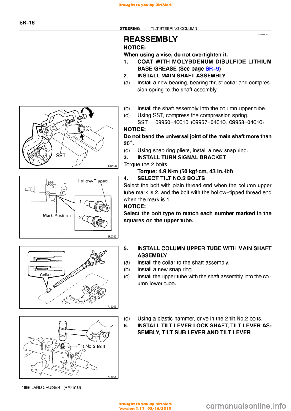
2. INSTALL MAIN SHAFT ASSEMBLY
(a) Install a new bearing, bearing thrust collar and compres- sion spring to the shaft assembly.
(b) Install the shaft assembly into the column upper tube.
(c) Using SST, compress the compression spring. SST 09950−40010 (09957 −04010, 09958−04010)
NOTICE:
Do not bend the universal joint of the main shaft more than
20 °.
(d) Using snap ring pliers, install a new snap ring.
3. INSTALL TURN SIGNAL BRACKET
Torque the 2 bolts. Torque: 4.9 N·m (50 kgf·cm, 43 in.·lbf)
4. SELECT TILT NO.2 BOLTS
Select the bolt with plain thread end when the column upper
tube mark is 2, and the bolt with the hollow −tipped thread end
when the mark is 1.
NOTICE:
Select the bolt type to match each number marked in the
squares on the upper tube.
5. INSTALL COLUMN UPPER TUBE WITH MAIN SHAFT ASSEMBLY
(a) Install the collar to the shaft assembly.
(b) Install a new snap ring.
(c) Install the upper tube with the shaft assembly into the col-
umn lower tube.
(d) Using a plastic hammer, drive in the 2 tilt No.2 bolts.
6. INSTALL TILT LEVER LOCK SHAFT, TILT LEVER AS- SEMBLY, TILT SUB LEVER AND TILT LEVER
Brought to you by BirfMark
Brought to you by BirfMark
Version 1.11 - 03/16/2010