Page 826 of 1399
EM0580
−
ENGINE MECHANICAL CYLINDER HEAD
EM−41
1996 LAND CRUISER (RM451U)
(d) Using a soft brush and solvent, thoroughly clean the cylin-
der head.
3. INSPECT CYLINDER HEAD
(a) Inspect for flatness. Using a precision straight edge and thickness gauge,
measure the surfaces contacting the cylinder block and
the manifolds for warpage.
Maximum warpage:
Cylinder block side0.15 mm (0.0059 in)
Manifold side0.10 mm (0.0039 in)
If warpage is greater than maximum, replace the cylinder head.
(b) Inspect for cracks.Using a dye penetrant, check the combustion chambers,
intake ports, exhaust ports and cylinder block surface for
cracks.
If cracked, replace the cylinder head.
4. CLEAN VALVES
(a) Using a gasket scraper, chip off any carbon from the valve head.
(b) Using a wire brush, thoroughly clean the valve.
Brought to you by BirfMark
Brought to you by BirfMark
Version 1.11 - 03/16/2010
Page 830 of 1399

EM0281
P03976
P03977
−
ENGINE MECHANICAL CYLINDER HEAD
EM−45
1996 LAND CRUISER (RM451U)
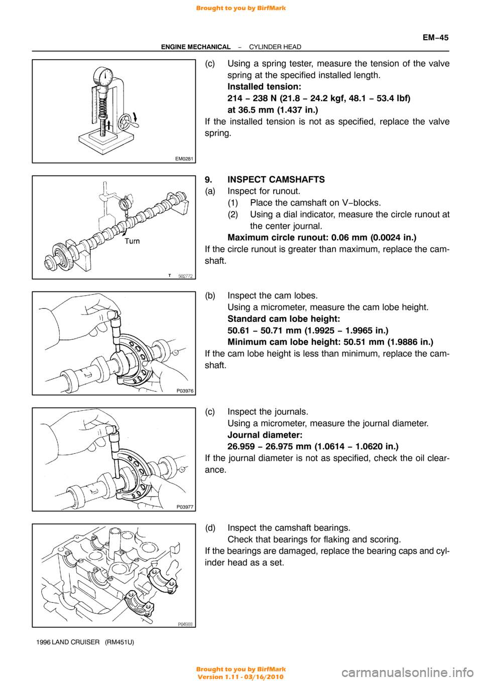
(c) Using a spring tester, measure the tension of the valve
spring at the specified installed length.
Installed tension:
214 − 238 N (21.8 − 24.2 kgf, 48.1 − 53.4 lbf)
at 36.5 mm (1.437 in.)
If the installed tension is not as specified, replace the valve
spring.
9. INSPECT CAMSHAFTS
(a) Inspect for runout. (1) Place the camshaft on V−blocks.
(2) Using a dial indicator, measure the circle runout atthe center journal.
Maximum circle runout: 0.06 mm (0.0024 in.)
If the circle runout is greater than maximum, replace the cam-
shaft.
(b) Inspect the cam lobes. Using a micrometer, measure the cam lobe height.
Standard cam lobe height:
50.61 − 50.71 mm (1.9925 − 1.9965 in.)
Minimum cam lobe height: 50.51 mm (1.9886 in.)
If the cam lobe height is less than minimum, replace the cam-
shaft.
(c) Inspect the journals. Using a micrometer, measure the journal diameter.
Journal diameter:
26.959 − 26.975 mm (1.0614 − 1.0620 in.)
If the journal diameter is not as specified, check the oil clear-
ance.
(d) Inspect the camshaft bearings. Check that bearings for flaking and scoring.
If the bearings are damaged, replace the bearing caps and cyl-
inder head as a set.
Brought to you by BirfMark
Brought to you by BirfMark
Version 1.11 - 03/16/2010
Page 839 of 1399

EM1E7−01
EM−54
−
ENGINE MECHANICAL CYLINDER HEAD
1996 LAND CRUISER (RM451U)
INSTALLATION
1. INSTALL CYLINDER HEAD AND INTAKE MANIFOLD ASSEMBLY
(a) Place the cylinder head on the cylinder head. (1) Apply seal packing to the 2 locations as shown.
Seal packing: Part No. 08826−00080 or equivalent
NOTICE:
Do not apply too much seal packing
(2) Place a new cylinder head gasket in position on the
cylinder block.
NOTICE:
Be careful of the installation direction. (3) Place the cylinder head in position on the cylinderhead gasket.
(b) Install the cylinder head bolts.
HINT:
�The cylinder head bolts are tightened in 3 progressive
steps (steps (b), (d) and (e)).
�If any cylinder head bolt is broken or deformed, replace
it.
(1) Apply a light coat of engine oil on the threads and under the heads of the cylinder head bolts.
(2) Install and uniformly tighten the 14 cylinder head
bolts and plate washers in several passes, in the se-
quence shown.
Torque: 39 N·m (400 kgf·cm, 29 ft·lbf)
If any of the cylinder head bolts does not meet the torque speci-
fication, replace the cylinder head bolt.
(3) Mark the front of the cylinder head bolt head withpaint.
(4) Retighten the cylinder head bolts by 90 ° in the nu-
merical order shown.
(5) Retighten the cylinder head bolts by an additional 90°.
(6) Check that the painted mark is now facing rearward.
Brought to you by BirfMark
Brought to you by BirfMark
Version 1.11 - 03/16/2010
Page 840 of 1399

−
ENGINE MECHANICAL CYLINDER HEAD
EM−55
1996 LAND CRUISER (RM451U)
(7) Install and torque the 2 mounting bolts.
Torque: 21N·m (210 kgf·cm, 15 ft·lbf)
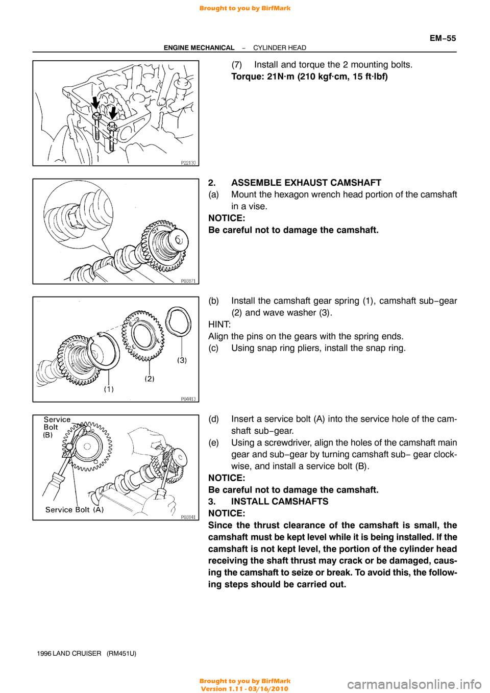
2. ASSEMBLE EXHAUST CAMSHAFT
(a) Mount the hexagon wrench head portion of the camshaft in a vise.
NOTICE:
Be careful not to damage the camshaft.
(b) Install the camshaft gear spring (1), camshaft sub −gear
(2) and wave washer (3).
HINT:
Align the pins on the gears with the spring ends.
(c) Using snap ring pliers, install the snap ring.
(d) Insert a service bolt (A) into the service hole of the cam- shaft sub−gear.
(e) Using a screwdriver, align the holes of the camshaft main
gear and sub− gear by turning camshaft sub − gear clock-
wise, and install a service bolt (B).
NOTICE:
Be careful not to damage the camshaft.
3. INSTALL CAMSHAFTS
NOTICE:
Since the thrust clearance of the camshaft is small, the
camshaft must be kept level while it is being installed. If the
camshaft is not kept level, the portion of the cylinder head
receiving the shaft thrust may crack or be damaged, caus-
ing the camshaft to seize or break. To avoid this, the follow-
ing steps should be carried out.
Brought to you by BirfMark
Brought to you by BirfMark
Version 1.11 - 03/16/2010
Page 844 of 1399

Front Mark
P09890
Push
P08374A16075
1 Dot Mark
−
ENGINE MECHANICAL CYLINDER HEAD
EM−59
1996 LAND CRUISER (RM451U)
6. INSTALL CHAIN TENSIONER
(a) Place a new gasket so that the front mark is toward the
front side.
(b) Push the tensioner by hand until it touches the head installation surface, then install the 2 nuts.
(c) Tighten the 2 nuts. Torque: 21 N·m (210 kgf·cm, 15 ft·lbf)
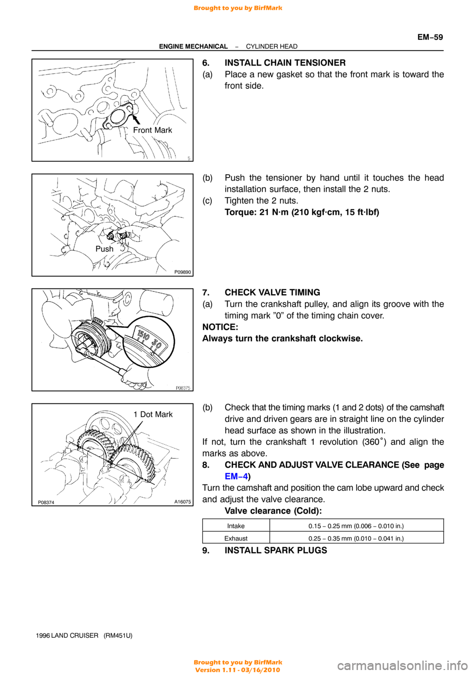
7. CHECK VALVE TIMING
(a) Turn the crankshaft pulley, and align its groove with the timing mark ”0” of the timing chain cover.
NOTICE:
Always turn the crankshaft clockwise.
(b) Check that the timing marks (1 and 2 dots) of the camshaft
drive and driven gears are in straight line on the cylinder
head surface as shown in the illustration.
If not, turn the crankshaft 1 revolution (360° ) and align the
marks as above.
8. CHECK AND ADJUST VALVE CLEARANCE (See page
EM−4)
Turn the camshaft and position the cam lobe upward and check
and adjust the valve clearance.
Valve clearance (Cold):
Intake0.15 − 0.25 mm (0.006 − 0.010 in.)
Exhaust0.25 − 0.35 mm (0.010 − 0.041 in.)
9. INSTALL SPARK PLUGS
Brought to you by BirfMark
Brought to you by BirfMark
Version 1.11 - 03/16/2010
Page 847 of 1399

EM−62
−
ENGINE MECHANICAL CYLINDER HEAD
1996 LAND CRUISER (RM451U)
(h) Connect the engine wire to the intake manifold and cylin-
der block with the 2 bolts.
(i) Connect the PNP switch connector.
(j) Connect the 2 heated oxygen sensor connectors.
(k) Connect the connectors.
(1) Connect the Knock sensor connector.
(2) Connect the oil level sensor connector.
(3) Connect the 2 connectors to tthe ransmission.
(4) Connect the starter connector.
(l) Connect the engine wire to the cylinder block with the bolt.
(m) Connect the connectors.
(1) Connect the ECT sender gauge connector.
(2) Connect the ECT cut switch connector.
(3) Connect the ECT sensor connector.
(4) Connect the knock sensor connector.
(5) Connect the crankshaft position sensor connector.
19. CONNECT FUEL INLET HOSE
Connect the fuel inlet hose to the fuel filter with 2 new gaskets
and the union bolt. Torque: 29 N·m (300 kgf·cm, 22 ft·lbf)
20. INSTALL INTAKE MANIFOLD STAY
Install the intake manifold stay with the 2 bolts. Torque: 36 N·m (360 kgf·cm, 26 ft·lbf)
21. INSTALL OIL DIPSTICKS AND GUIDES FOR ENGINE AND TRANSMISSION
(a) Install a new O−ring to the dipstick guide.
(b) Apply a light coat of engine oil on the O −ring.
(c) Push in the dipstick guide into the guide hole of the oil pan.
(d) Install the dipstick guide with the 2 bolts. Torque: 20 N·m (200 kgf·cm, 14 ft·lbf)
22. INSTALL THROTTLE BODY (See page SF−48)
23. INSTALL GENERATOR AND DRIVE BELTS (See page CH−19 )
Brought to you by BirfMark
Brought to you by BirfMark
Version 1.11 - 03/16/2010
Page 855 of 1399

EM−70
−
ENGINE MECHANICAL ENGINE UNIT
1996 LAND CRUISER (RM451U)
13. DISCONNECT ENGINE WIRE AND HEATER VALVE
FROM COWL PANEL
(a) Remove the 2 bolts and disconnect the engine wire and
ground strap.
(b) Remove the 2 bolts and disconnect the heater valve.
14. DISCONNECT BRAKE BOOSTER VACUUM HOSE
15. DISCONNECT EVAP HOSE
16. DISCONNECT FUEL HOSES
(a) Disconnect the fuel return hose.
(b) Remove the union bolt and 2 gaskets, and disconnect the
fuel inlet hose from the fuel filter.
17. DISCONNECT WIRES AND CONNECTORS
(a) Disconnect the 2 heated oxygen sensor connectors.
(b) Disconnect the DLC1 clamp.
(c) Disconnect the 2 oil pressure gauge connectors.
(d) Disconnect the generator wire and connector.
(e) Disconnect the connector on the intake manifold from the
fender apron.
(f) Disconnect the high−tension cord from the ignition coil.
(g) Disconnect the ground strap from the No. 1 engine hang-
er.
(h) Disconnect the ground strap from the air intake chamber.
(i) Disconnect the starter wire.
(j) Disconnect the ground cable from the cylinder block.
18. DISCONNECT A/C COMPRESSOR AND BRACKET
(a) Loosen the idler pulley nut and adjusting bolt, and remove
the drive belt.
(b) Remove the 4 mounting bolts, and disconnect the com-
pressor from the bracket.
HINT:
Put aside the compressor, and suspend it.
(c) Remove the 5 bolts and A/C compressor bracket.
19. REMOVE RADIATOR PIPE
(a) Remove the 2 nuts holding the radiator pipe to the No. 1 oil pan.
(b) Disconnect the No. 2 radiator hose from the water inlet and remove the radiator pipe.
Brought to you by BirfMark
Brought to you by BirfMark
Version 1.11 - 03/16/2010
Page 858 of 1399

−
ENGINE MECHANICAL ENGINE UNIT
EM−73
1996 LAND CRUISER (RM451U)
(g) Disconnect the 3 connectors.
(h) Remove the 10 bolts and the transfer shift lever boot and
transmission shift lever assembly.
(i) Pull out the pin and disconnect the shift rod.
(j) Remove the 4 bolts, hose clamp and the transfer shift le- ver.
26. REMOVE FRONT EXHAUST PIPE
(a) Disconnect the heated oxygen sensor connector.
(b) Remove the 2 nuts and 2 bolts holding the front exhaust pipe to the rear TWC.
(c) Disconnect the front exhaust pipe, and remove the gas- ket.
(d) Loosen the clamp bolt and disconnect the clamp from the
No.1 support bracket.
(e) Remove the 2 bolts and No. 1 support bracket.
(f) Remove the 4 nuts, front exhaust pipe and 2 gaskets.
27. DISCONNECT GROUND STRAP FROM HEAT INSULA-
TOR
28. PLACE JACK UNDER TRANSMISSION
Be sure to put a wooden block between the jack and the trans-
mission oil pan to prevent damage.
Brought to you by BirfMark
Brought to you by BirfMark
Version 1.11 - 03/16/2010