Page 783 of 1399

(a)
(b)
(c)
−
EMISSION CONTROL EXHAUST GAS RECIRCULATION (EGR) SYSTEM
EC−13
1996 LAND CRUISER (RM451U)
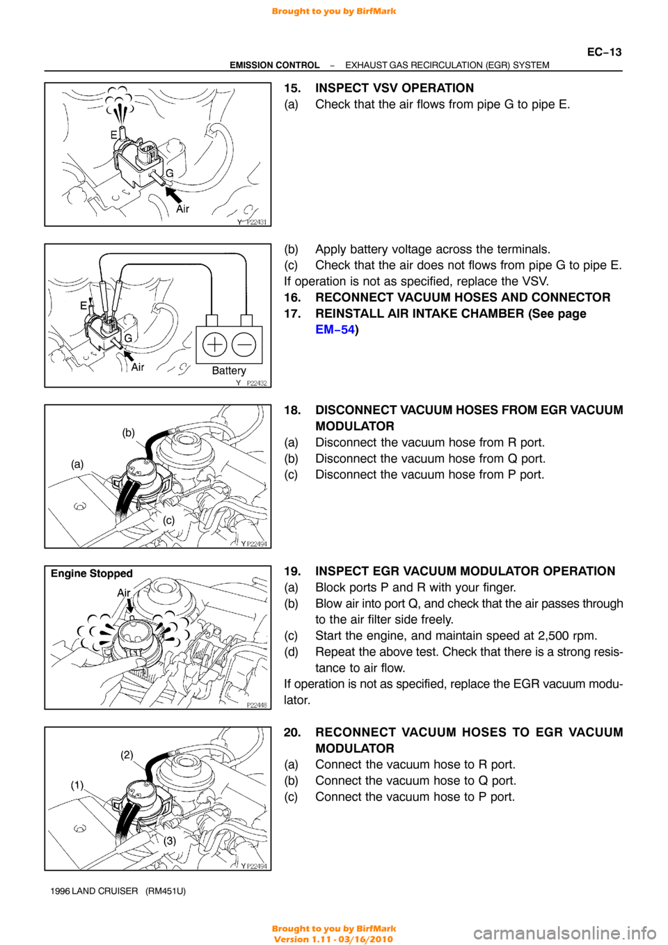
15. INSPECT VSV OPERATION
(a) Check that the air flows from pipe G to pipe E.
(b) Apply battery voltage across the terminals.
(c) Check that the air does not flows from pipe G to pipe E.
If operation is not as specified, replace the VSV.
16. RECONNECT VACUUM HOSES AND CONNECTOR
17. REINSTALL AIR INTAKE CHAMBER (See page
EM−54 )
18. DISCONNECT V ACUUM HOSES FROM EGR V ACUUM
MODULATOR
(a) Disconnect the vacuum hose from R port.
(b) Disconnect the vacuum hose from Q port.
(c) Disconnect the vacuum hose from P port.
19. INSPECT EGR VACUUM MODULATOR OPERATION
(a) Block ports P and R with your finger.
(b) Blow air into port Q, and check that the air passes through
to the air filter side freely.
(c) Start the engine, and maintain speed at 2,500 rpm.
(d) Repeat the above test. Check that there is a strong resis-
tance to air flow.
If operation is not as specified, replace the EGR vacuum modu-
lator.
20. RECONNECT VACUUM HOSES TO EGR VACUUM
MODULATOR
(a) Connect the vacuum hose to R port.
(b) Connect the vacuum hose to Q port.
(c) Connect the vacuum hose to P port.
Brought to you by BirfMark
Brought to you by BirfMark
Version 1.11 - 03/16/2010
Page 800 of 1399

−
ENGINE MECHANICAL TIMING CHAIN
EM−15
1996 LAND CRUISER (RM451U)
15. CHECK THRUST CLEARANCE OF OIL PUMP DRIVE
SHAFT GEAR
Using a dial indicator with lever type attachment, measure the
thrust clearance.
Standard thrust clearance:
0.040 − 0.160 mm (0.0016 − 0.0063 in.)
Maximum thrust clearance: 0.30 mm (0.0118 in.)
If the thrust clearance is greater than maximum, replace the oil
pump drive shaft gear and/or timing chain cover.
16. REMOVE DRIVE BELT IDLER PULLEY
Remove the bolt and idler pulley.
17. REMOVE TIMING CHAIN COVER
(a) Remove the 9 mounting bolts, 2 mounting nuts and drive belt adjusting bar.
(b) Remove the oil pump by prying the portions between the cylinder block and oil pump with a screwdriver.
NOTICE:
Be careful not to damage the contact surfaces of the cylin-
der block and oil pump.
(c) Remove the O−rings from the oil pump.
(d) Remove the gasket from the oil pump.
18. REMOVE TIMING CHAIN AND CAMSHAFT TIMING GEAR
Brought to you by BirfMark
Brought to you by BirfMark
Version 1.11 - 03/16/2010
Page 806 of 1399

−
ENGINE MECHANICAL TIMING CHAIN
EM−21
1996 LAND CRUISER (RM451U)
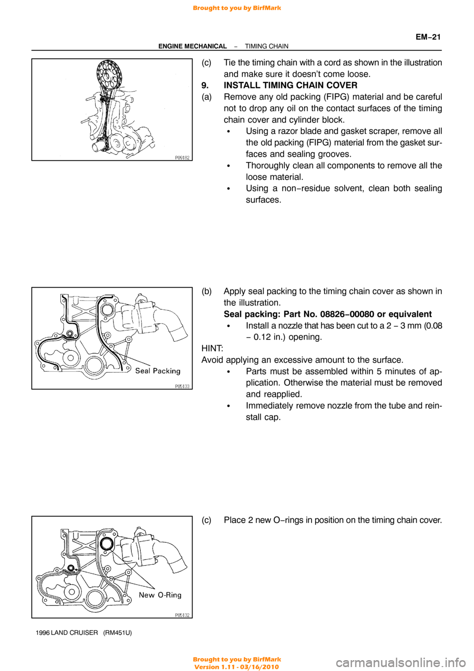
(c) Tie the timing chain with a cord as shown in the illustration
and make sure it doesn’t come loose.
9. INSTALL TIMING CHAIN COVER
(a) Remove any old packing (FIPG) material and be careful
not to drop any oil on the contact surfaces of the timing
chain cover and cylinder block.
�Using a razor blade and gasket scraper, remove all
the old packing (FIPG) material from the gasket sur-
faces and sealing grooves.
�Thoroughly clean all components to remove all the
loose material.
�Using a non −residue solvent, clean both sealing
surfaces.
(b) Apply seal packing to the timing chain cover as shown in the illustration.
Seal packing: Part No. 08826−00080 or equivalent
�Install a nozzle that has been cut to a 2 − 3 mm (0.08
− 0.12 in.) opening.
HINT:
Avoid applying an excessive amount to the surface.
�Parts must be assembled within 5 minutes of ap-
plication. Otherwise the material must be removed
and reapplied.
�Immediately remove nozzle from the tube and rein-
stall cap.
(c) Place 2 new O− rings in position on the timing chain cover.
Brought to you by BirfMark
Brought to you by BirfMark
Version 1.11 - 03/16/2010
Page 814 of 1399

−
ENGINE MECHANICAL CYLINDER HEAD
EM−29
1996 LAND CRUISER (RM451U)
16. DISCONNECT PS RESERVOIR TANK
Remove the 3 bolts and disconnect the reservoir tank.
17. DISCONNECT RADIATOR INLET HOSE
18. DISCONNECT NO. 3 WATER BYPASS HOSE
19. REMOVE GENERATOR (See page CH−8 )
20. REMOVE THROTTLE BODY (See page SF−45)
21. REMOVE OIL DIPSTICKS AND GUIDES FOR ENGINE AND TRANSMISSION
(a) Remove the 2 mounting bolts.
(b) Pull out the dipstick together with dipstick guide.
(c) Remove the O−ring from the dipstick guide.
22. REMOVE INTAKE MANIFOLD STAY
Remove the 2 bolts and intake manifold stay.
23. DISCONNECT FUEL INLET HOSE
Remove the union bolt and 2 gaskets, and disconnect the fuel
inlet hose from the fuel filter.
24. DISCONNECT ENGINE WIRE
(a) Disconnect the connectors. (1) Disconnect the ECT sender gauge connector.
(2) Disconnect the ECT cut switch connector.
(3) Disconnect the ECT sensor connector.
(4) Disconnect the knock sensor connector.
(5) Disconnect the crankshaft position sensor connec-tor.
(6) Remove the bolt and disconnect the engine wire from the cylinder block.
Brought to you by BirfMark
Brought to you by BirfMark
Version 1.11 - 03/16/2010
Page 815 of 1399

EM−30
−
ENGINE MECHANICAL CYLINDER HEAD
1996 LAND CRUISER (RM451U)
(b) Disconnect the connectors.
(1) Disconnect the knock sensor connector.
(2) Disconnect the oil level sensor connector.
(3) Disconnect the 2 connectors from the transmission.
(4) Disconnect the starter connector.
(c) Disconnect the 2 heated oxygen sensor connectors.
(d) Disconnect the PNP switch connector.
(e) Remove the 2 bolts and disconnect the engine wire from the intake manifold and cylinder block.
(f) Disconnect the PCV hose from the PCV valve.
(g) Remove the bolt holding the engine wire to the intake manifold.
(h) Disconnect the connectors. (1) Disconnect the connector for the emission controlvalve set assembly.
(2) Disconnect the 3 injector connectors.
(i) Disconnect the engine wire clamp.
(j) Disconnect the engine wire clamp.
(k) Disconnect the connectors.
(1) Disconnect the 3 injector connectors.
(2) Disconnect the EGR gas temp. sensor connector.
(l) Disconnect the clamp of the No. 6 injector wire from the bracket.
(m) Disconnect the engine wire from the cylinder head and in-
take manifold.
25. DISCONNECT NO. 2 WATER BYPASS PIPE
Remove the 3 bolts, and disconnect the bypass pipe from the
cylinder head.
Brought to you by BirfMark
Brought to you by BirfMark
Version 1.11 - 03/16/2010
Page 820 of 1399

−
ENGINE MECHANICAL CYLINDER HEAD
EM−35
1996 LAND CRUISER (RM451U)
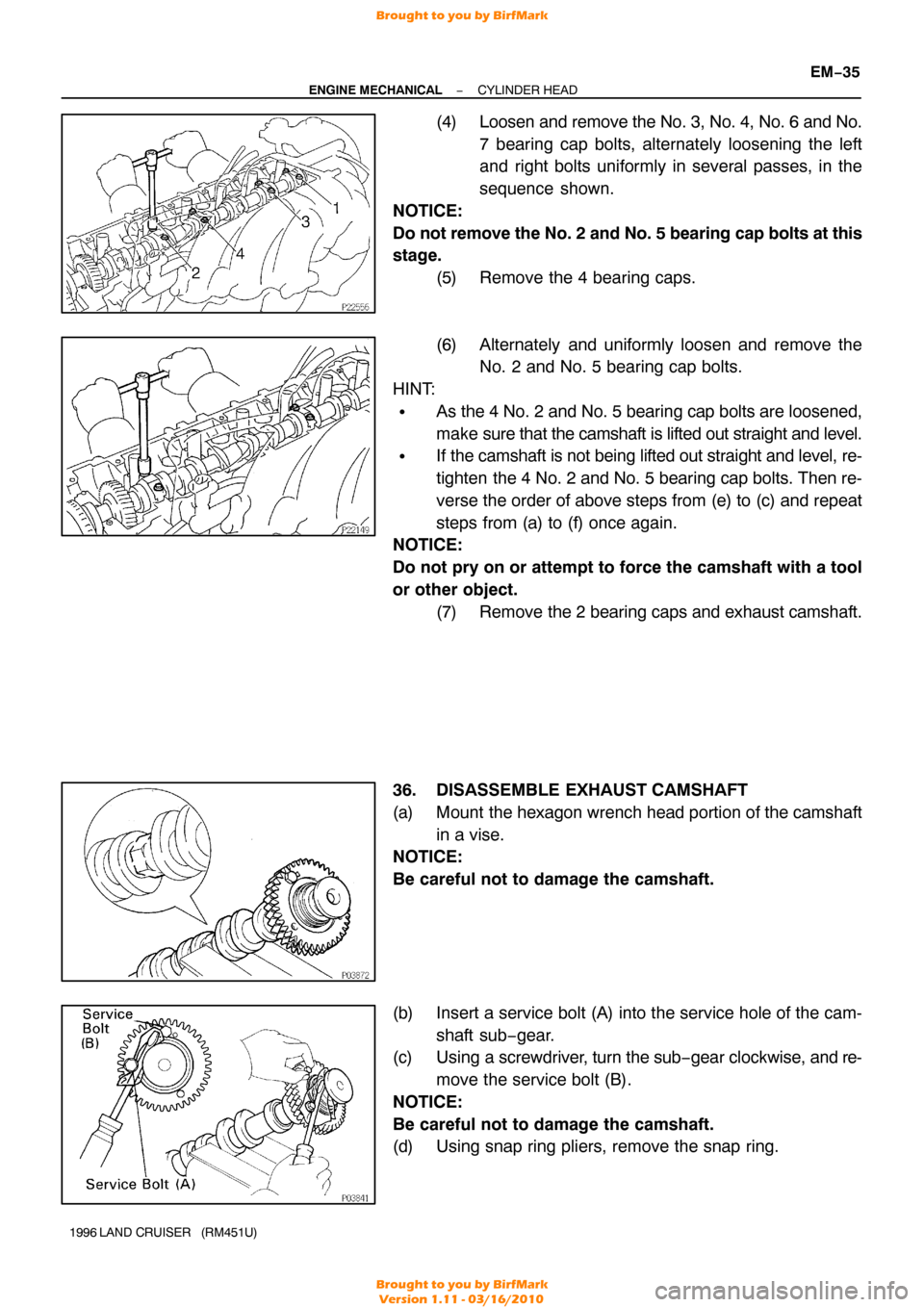
(4) Loosen and remove the No. 3, No. 4, No. 6 and No.
7 bearing cap bolts, alternately loosening the left
and right bolts uniformly in several passes, in the
sequence shown.
NOTICE:
Do not remove the No. 2 and No. 5 bearing cap bolts at this
stage. (5) Remove the 4 bearing caps.
(6) Alternately and uniformly loosen and remove theNo. 2 and No. 5 bearing cap bolts.
HINT:
�As the 4 No. 2 and No. 5 bearing cap bolts are loosened,
make sure that the camshaft is lifted out straight and level.
�If the camshaft is not being lifted out straight and level, re-
tighten the 4 No. 2 and No. 5 bearing cap bolts. Then re-
verse the order of above steps from (e) to (c) and repeat
steps from (a) to (f) once again.
NOTICE:
Do not pry on or attempt to force the camshaft with a tool
or other object.
(7) Remove the 2 bearing caps and exhaust camshaft.
36. DISASSEMBLE EXHAUST CAMSHAFT
(a) Mount the hexagon wrench head portion of the camshaft in a vise.
NOTICE:
Be careful not to damage the camshaft.
(b) Insert a service bolt (A) into the service hole of the cam-
shaft sub−gear.
(c) Using a screwdriver, turn the sub− gear clockwise, and re-
move the service bolt (B).
NOTICE:
Be careful not to damage the camshaft.
(d) Using snap ring pliers, remove the snap ring.
Brought to you by BirfMark
Brought to you by BirfMark
Version 1.11 - 03/16/2010
Page 821 of 1399
EM−36
−
ENGINE MECHANICAL CYLINDER HEAD
1996 LAND CRUISER (RM451U)
(e) Remove the wave washer (1), camshaft sub− gear (2) and
camshaft gear spring (3).
37. REMOVE CYLINDER HEAD AND INTAKE MANIFOLD ASSEMBLY
(a) Remove the 2 bolts in front of the head before the other head bolts are removed.
(b) Uniformly loosen and remove the 14 cylinder head bolts, in several passes, in the sequence shown.
NOTICE:
Cylinder head warpage or cracking could result from re-
moving bolts in incorrect order.
(c) Lift the cylinder head from the dowels on the cylinder block, and place the cylinder head on wooden blocks on
a bench.
HINT:
If the cylinder head is difficult to lift off, pry between the cylinder
head and cylinder block with a screwdriver.
NOTICE:
Be careful not to damage the contact surfaces of the cylin-
der head and cylinder block.
Brought to you by BirfMark
Brought to you by BirfMark
Version 1.11 - 03/16/2010
Page 825 of 1399

EM1Q7−01
EM−40
−
ENGINE MECHANICAL CYLINDER HEAD
1996 LAND CRUISER (RM451U)
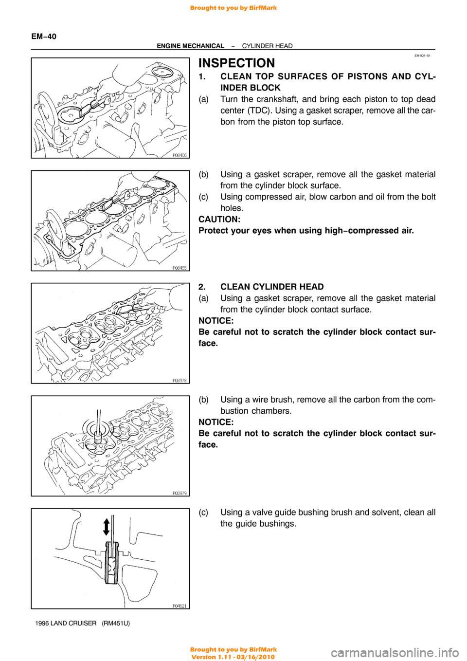
INSPECTION
1. CLE AN TO P SURFACE S OF PIS TO NS AND CY L- INDER BLOCK
(a) Turn the crankshaft, and bring each piston to top dead center (TDC). Using a gasket scraper, remove all the car-
bon from the piston top surface.
(b) Using a gasket scraper, remove all the gasket material from the cylinder block surface.
(c) Using compressed air, blow carbon and oil from the bolt holes.
CAUTION:
Protect your eyes when using high −compressed air.
2. CLEAN CYLINDER HEAD
(a) Using a gasket scraper, remove all the gasket material from the cylinder block contact surface.
NOTICE:
Be careful not to scratch the cylinder block contact sur-
face.
(b) Using a wire brush, remove all the carbon from the com- bustion chambers.
NOTICE:
Be careful not to scratch the cylinder block contact sur-
face.
(c) Using a valve guide bushing brush and solvent, clean all the guide bushings.
Brought to you by BirfMark
Brought to you by BirfMark
Version 1.11 - 03/16/2010