Page 845 of 1399

P03789
P08374A16075
1 Dot Mark
EM−60
−
ENGINE MECHANICAL CYLINDER HEAD
1996 LAND CRUISER (RM451U)
10. INSTALL SEMI −CIRCULAR PLUG
(a) Remove any old packing (FIPG) material.
(b) Apply seal packing to the cylinder head installation sur- face of the semi−circular plug.
Seal packing: Part No. 08826−00080 or equivalent
(c) Install the semi −circular plug to the cylinder head.
11. SET NO. 1 CYLINDER TO TDC/COMPRESSION
(a) Turn the crankshaft pulley, and align its groove with the timing mark ”0” of the timing chain cover.
(b) Check that the timing marks with 1 and 2 dots are in straight line on the cylinder head surface as shown in the
illustration.
If not, turn the crankshaft 1 revolution (360°) and align the mark
as above.
12. INSTALL CYLINDER HEAD COVER
(a) Install the gasket to the cylinder head cover.
(b) Install the cylinder head cover with the 13 bolts.
13. INSTALL WATER BYPASS OUTLET AND PIPE
(a) Install a new O−ring to the water bypass outlet.
(b) Install 2 new O−rings to the water bypass pipe.
(c) Apply soapy water to the O−rings.
(d) Assemble the water bypass outlet and pipe.
(e) Install the water bypass outlet and pipe with the 2 bolts.
Torque: 21 N·m (210 kgf·cm, 15 ft·lbf)
Brought to you by BirfMark
Brought to you by BirfMark
Version 1.11 - 03/16/2010
Page 849 of 1399
EM−64
−
ENGINE MECHANICAL CYLINDER HEAD
1996 LAND CRUISER (RM451U)
39. INSTALL AIR CLEANER HOSE AND CAP
40. INSTALL BATTERY TRAY AND BATTERY
(a) Install the battery tray with the 5 bolts.
(b) Connect the ground strap with the bolt.
(c) Install the battery and hold−down clamp with the nuts.
(d) Connect the battery cables.
41. FILL RADIATOR WITH ENGINE COOLANT
42. START ENGINE AND CHECK FOR LEAKS
43. ADJUST IGNITION TIMING (See page EM−10)
44. PERFORM ROAD TEST
Check for abnormal noise, shock, slippage, correct shift points
and smooth operation.
45. RECHECK ENGINE COOLANT LEVEL
Brought to you by BirfMark
Brought to you by BirfMark
Version 1.11 - 03/16/2010
Page 861 of 1399

EM1EE−02
EM−76
−
ENGINE MECHANICAL ENGINE UNIT
1996 LAND CRUISER (RM451U)
INSTALLATION
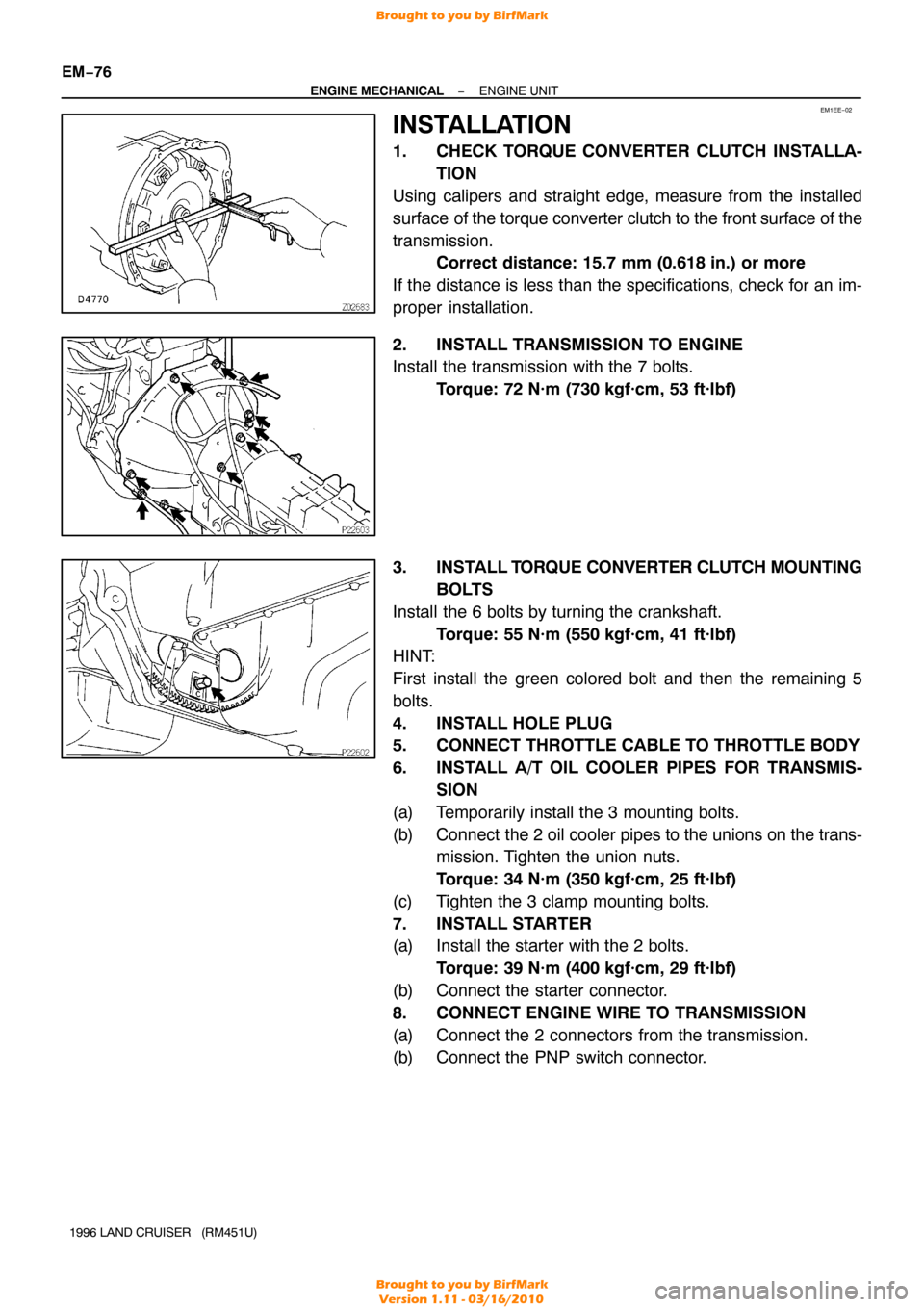
1. CHECK TORQUE CONVERTER CLUTCH INSTALLA- TION
Using calipers and straight edge, measure from the installed
surface of the torque converter clutch to the front surface of the
transmission. Correct distance: 15.7 mm (0.618 in.) or more
If the distance is less than the specifications, check for an im-
proper installation.
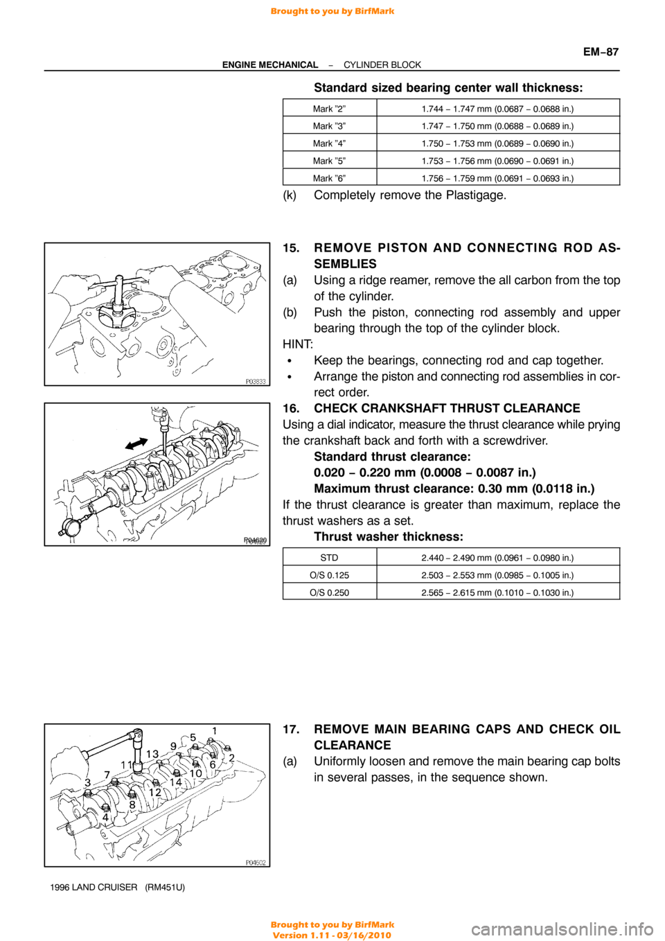
2. INSTALL TRANSMISSION TO ENGINE
Install the transmission with the 7 bolts. Torque: 72 N·m (730 kgf·cm, 53 ft·lbf)
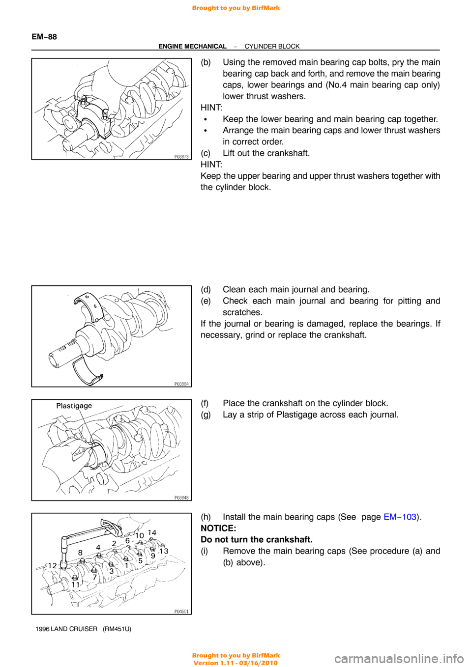
3. INSTALL T ORQUE CONVERTER CLUTCH MOUNTING
BOLTS
Install the 6 bolts by turning the crankshaft. Torque: 55 N·m (550 kgf·cm, 41 ft·lbf)
HINT:
First install the green colored bolt and then the remaining 5
bolts.
4. INSTALL HOLE PLUG
5. CONNECT THROTTLE CABLE TO THROTTLE BODY
6. INSTALL A/T OIL COOLER PIPES FOR TRANSMIS-
SION
(a) Temporarily install the 3 mounting bolts.
(b) Connect the 2 oil cooler pipes to the unions on the trans-
mission. Tighten the union nuts.
Torque: 34 N·m (350 kgf·cm, 25 ft·lbf)
(c) Tighten the 3 clamp mounting bolts.
7. INSTALL STARTER
(a) Install the starter with the 2 bolts. Torque: 39 N·m (400 kgf·cm, 29 ft·lbf)
(b) Connect the starter connector.
8. CONNECT ENGINE WIRE TO TRANSMISSION
(a) Connect the 2 connectors from the transmission.
(b) Connect the PNP switch connector.
Brought to you by BirfMark
Brought to you by BirfMark
Version 1.11 - 03/16/2010
Page 866 of 1399

−
ENGINE MECHANICAL ENGINE UNIT
EM−81
1996 LAND CRUISER (RM451U)
26. CONNECT EVAP HOSE
27. CONNECT BRAKE BOOSTER VACUUM HOSE
28. CONNECT HEATER VALVE AND ENGINE WIRE TO
COWL PANEL
(a) Connect the heater valve with the 2 bolts.
(b) Connect the engine wire and ground strap with the 2 bolts.
29. CONNECT HEATER HOSES
30. CONNECT ACCELERATOR CABLE TO THROTTLE BODY
31. CONNECT CRUISE CONTROL ACTUATOR CABLE TO
THROTTLE BODY
32. INSTALL AIR CLEANER CASE
33. INSTALL AIR CLEANER HOSE AND CAP
34. CONNECT OIL COOLER HOSE TO OIL COOLER PIPE
35. INSTALL RADIATOR (See page CO−16)
36. INSTALL RADIATOR GRILLE
Install the radiator grille with the 5 screws and clip.
37. INSTALL BATTERY TRAY AND BATTERY
(a) Install the battery tray with the 5 bolts.
(b) Connect the ground strap with the bolt.
(c) Install the battery and hold−down clamp with the nuts.
(d) Connect the battery cables.
38. FILL WITH ENGINE OIL
39. FILL RADIATOR WITH ENGINE COOLANT
40. START ENGINE AND CHECK FOR LEAKS
41. CHECK AUTOMATIC TRANSMISSION FLUID LEVEL
42. CHECK IGNITION TIMING (See page EM−10)
43. INSTALL HOOD
44. PERFORM ROAD TEST
Check for abnormal noise, shock, slippage, correct shift points
and smooth operation.
45. RECHECK ENGINE COOLANT AND ENGINE OIL LEV-
ELS
Brought to you by BirfMark
Brought to you by BirfMark
Version 1.11 - 03/16/2010
Page 869 of 1399
EM−84
−
ENGINE MECHANICAL CYLINDER BLOCK
1996 LAND CRUISER (RM451U)
9. REMOVE RH ENGINE MOUNTING BRACKET
(a) Remove the nut and insulator.
(b) Remove the 4 bolts and bracket.
10. REMOVE LH ENGINE MOUNTING BRACKET
(a) Remove the nut and insulator.
(b) Remove the 4 bolts and bracket.
11. REMOVE OIL COOLER COVER AND OIL COOLER
Remove the 10 bolts, 2 nuts, oil cooler cover with the oil cooler
and gasket.
12. REMOVE REAR OIL SEAL RETAINER
Remove the 4 bolts and retainer.
13. CHECK CONNECTING ROD THRUST CLEARANCE
Using a dial indicator, measure the thrust clearance while mov-
ing the connecting rod back and forth.
Standard thrust clearance:
0.160 − 0.262 mm (0.0063 − 0.0103 in.)
Maximum thrust clearance: 0.362 mm (0.0143 in.)
If the thrust clearance is greater than maximum, replace the
connecting rod assembly. If necessary , replace the crankshaft.
Brought to you by BirfMark
Brought to you by BirfMark
Version 1.11 - 03/16/2010
Page 870 of 1399
−
ENGINE MECHANICAL CYLINDER BLOCK
EM−85
1996 LAND CRUISER (RM451U)
14. REMOVE CONNECTING ROD CAPS AND CHECK OIL
CLEARANCE
(a) Check the matchmarks on the connecting rod cap and
connecting rod to ensure correct reassembly.
(b) Remove the connecting rod cap nuts.
(c) Using a plastic− faced hammer, lightly tap the connecting
rod bolts and lift off the connecting rod cap.
HINT:
Keep the lower bearing inserted with the connecting rod cap.
(d) Cover the connecting rod bolts with a short piece of hose to protect the crankshaft from damage.
(e) Clean the crank pin and bearing.
(f) Check the crank pin and bearing for pitting and scratches.
If the crank pin or bearing is damaged, replace the bearings. If
necessary, grind or replace the crankshaft.
(g) Lay a strip of Plastigage across the crank pin.
Brought to you by BirfMark
Brought to you by BirfMark
Version 1.11 - 03/16/2010
Page 872 of 1399

P04620
−
ENGINE MECHANICAL CYLINDER BLOCK
EM−87
1996 LAND CRUISER (RM451U)
Standard sized bearing center wall thickness:
Mark ”2”1.744 − 1.747 mm (0.0687 − 0.0688 in.)
Mark ”3”1.747 − 1.750 mm (0.0688 − 0.0689 in.)
Mark ”4”1.750 − 1.753 mm (0.0689 − 0.0690 in.)
Mark ”5”1.753 − 1.756 mm (0.0690 − 0.0691 in.)
Mark ”6”1.756 − 1.759 mm (0.0691 − 0.0693 in.)
(k) Completely remove the Plastigage.
15. R E M O V E P I S TO N A N D C O N N E C T I N G R O D A S-
SEMBLIES
(a) Using a ridge reamer, remove the all carbon from the top of the cylinder.
(b) Push the piston, connecting rod assembly and upper bearing through the top of the cylinder block.
HINT:
�Keep the bearings, connecting rod and cap together.
�Arrange the piston and connecting rod assemblies in cor-
rect order.
16. CHECK CRANKSHAFT THRUST CLEARANCE
Using a dial indicator, measure the thrust clearance while prying
the crankshaft back and forth with a screwdriver. Standard thrust clearance:
0.020 − 0.220 mm (0.0008 − 0.0087 in.)
Maximum thrust clearance: 0.30 mm (0.0118 in.)
If the thrust clearance is greater than maximum, replace the
thrust washers as a set. Thrust washer thickness:
STD2.440 − 2.490 mm (0.0961 − 0.0980 in.)
O/S 0.1252.503 − 2.553 mm (0.0985 − 0.1005 in.)
O/S 0.2502.565 − 2.615 mm (0.1010 − 0.1030 in.)
17. REMOVE MAIN BEARING CAPS AND CHECK OIL
CLEARANCE
(a) Uniformly loosen and remove the main bearing cap bolts
in several passes, in the sequence shown.
Brought to you by BirfMark
Brought to you by BirfMark
Version 1.11 - 03/16/2010
Page 873 of 1399

EM−88
−
ENGINE MECHANICAL CYLINDER BLOCK
1996 LAND CRUISER (RM451U)
(b) Using the removed main bearing cap bolts, pry the main
bearing cap back and forth, and remove the main bearing
caps, lower bearings and (No.4 main bearing cap only)
lower thrust washers.
HINT:
�Keep the lower bearing and main bearing cap together.
�Arrange the main bearing caps and lower thrust washers
in correct order.
(c) Lift out the crankshaft.
HINT:
Keep the upper bearing and upper thrust washers together with
the cylinder block.
(d) Clean each main journal and bearing.
(e) Check each main journal and bearing for pitting and
scratches.
If the journal or bearing is damaged, replace the bearings. If
necessary, grind or replace the crankshaft.
(f) Place the crankshaft on the cylinder block.
(g) Lay a strip of Plastigage across each journal.
(h) Install the main bearing caps (See page EM−103).
NOTICE:
Do not turn the crankshaft.
(i) Remove the main bearing caps (See procedure (a) and (b) above).
Brought to you by BirfMark
Brought to you by BirfMark
Version 1.11 - 03/16/2010