Page 800 of 1399

−
ENGINE MECHANICAL TIMING CHAIN
EM−15
1996 LAND CRUISER (RM451U)
15. CHECK THRUST CLEARANCE OF OIL PUMP DRIVE
SHAFT GEAR
Using a dial indicator with lever type attachment, measure the
thrust clearance.
Standard thrust clearance:
0.040 − 0.160 mm (0.0016 − 0.0063 in.)
Maximum thrust clearance: 0.30 mm (0.0118 in.)
If the thrust clearance is greater than maximum, replace the oil
pump drive shaft gear and/or timing chain cover.
16. REMOVE DRIVE BELT IDLER PULLEY
Remove the bolt and idler pulley.
17. REMOVE TIMING CHAIN COVER
(a) Remove the 9 mounting bolts, 2 mounting nuts and drive belt adjusting bar.
(b) Remove the oil pump by prying the portions between the cylinder block and oil pump with a screwdriver.
NOTICE:
Be careful not to damage the contact surfaces of the cylin-
der block and oil pump.
(c) Remove the O−rings from the oil pump.
(d) Remove the gasket from the oil pump.
18. REMOVE TIMING CHAIN AND CAMSHAFT TIMING GEAR
Brought to you by BirfMark
Brought to you by BirfMark
Version 1.11 - 03/16/2010
Page 802 of 1399

P04776
146.6 mm16 Links
EM1EA−01
P03876
−
ENGINE MECHANICAL TIMING CHAIN
EM−17
1996 LAND CRUISER (RM451U)
INSPECTION
1. INSPECT TIMING CHAIN AND TIMING GEARS
(a) Measure the length of 16 links with the chain fully
stretched.
Maximum chain elongation: 146.6 mm (5.772 in.)
If the elongation is greater than maximum, replace the chain.
HINT:
Make the same measurements pulling at 3 or more places se-
lected at random.
(b) Wrap the chain around the timing gear.
(c) Using vernier calipers, measure the timing gear diameter with the chain.
NOTICE:
Vernier calipers must contact the chain rollers for measur-
ing.
Minimum gear diameter (w/Chain):
Camshaft126.0 mm (4.961 in.)
Crankshaft65.4 mm (2.575 in.)
If the diameter is less than minimum, replace the chain and
gears.
2. INSPECT CHAIN TENSIONER SLIPPER AND VIBRA-TION DAMPER
Measure the chain tensioner slipper and vibration damper
wears. Maximum wear: 1.0 mm (0.039 in.)
If the wear is greater than maximum, replace the slipper and/or
damper.
3. INSPECT OIL JET
Check the oil jet for damage or clogging.
If necessary, replace the oil jet.
Brought to you by BirfMark
Brought to you by BirfMark
Version 1.11 - 03/16/2010
Page 805 of 1399
EM−20
−
ENGINE MECHANICAL TIMING CHAIN
1996 LAND CRUISER (RM451U)
(c) Check that the slipper moves smoothly.
7. INSTALL CRANKSHAFT TIMING GEAR
NOTICE:
Be careful of the installation direction.
HINT:
If necessary, install the gear with SST.
SST 09636−20010
8. INSTALL TIMING CHAIN AND CAMSHAFT TIMING GEAR
(a) Install the timing chain on the camshaft timing gear with the bright link aligned with the timing mark on the cam-
shaft timing gear.
(b) Install the timing chain on the crankshaft timing gear with the other bright link aligned with the timing mark on the
crankshaft timing gear.
Brought to you by BirfMark
Brought to you by BirfMark
Version 1.11 - 03/16/2010
Page 808 of 1399

−
ENGINE MECHANICAL TIMING CHAIN
EM−23
1996 LAND CRUISER (RM451U)
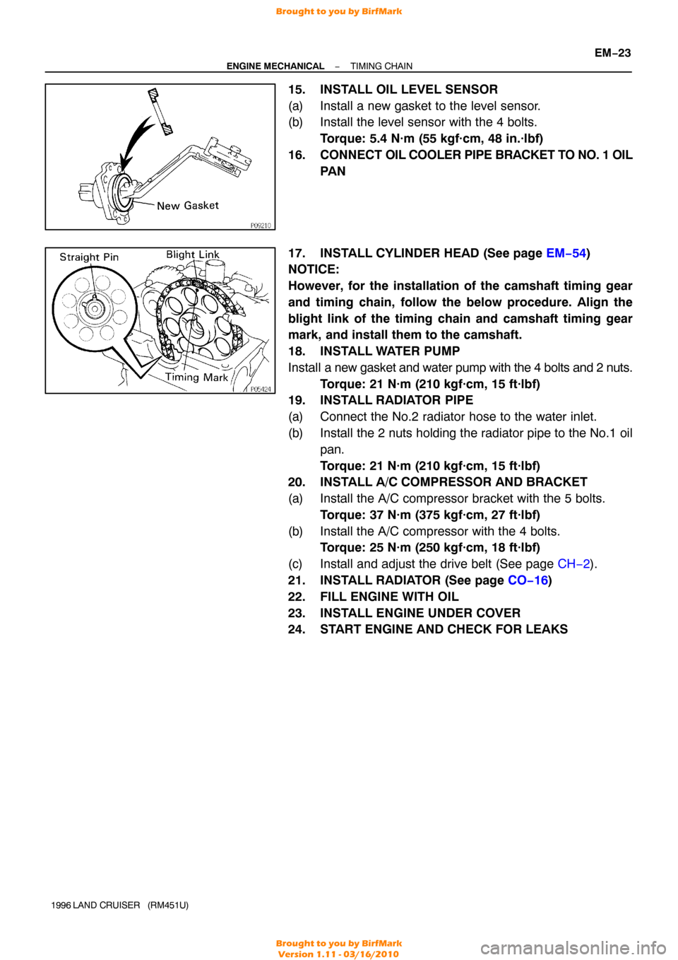
15. INSTALL OIL LEVEL SENSOR
(a) Install a new gasket to the level sensor.
(b) Install the level sensor with the 4 bolts.
Torque: 5.4 N·m (55 kgf·cm, 48 in.·lbf)
16. CONNECT OIL COOLER PIPE BRACKET TO NO. 1 OIL
PA N
17. INSTALL CYLINDER HEAD (See page EM−54 )
NOTICE:
However, for the installation of the camshaft timing gear
and timing chain, follow the below procedure. Align the
blight link of the timing chain and camshaft timing gear
mark, and install them to the camshaft.
18. INSTALL WATER PUMP
Install a new gasket and water pump with the 4 bolts and 2 nuts.
Torque: 21 N·m (210 kgf·cm, 15 ft·lbf)
19. INSTALL RADIATOR PIPE
(a) Connect the No.2 radiator hose to the water inlet.
(b) Install the 2 nuts holding the radiator pipe to the No.1 oil
pan.
Torque: 21 N·m (210 kgf·cm, 15 ft·lbf)
20. INSTALL A/C COMPRESSOR AND BRACKET
(a) Install the A/C compressor bracket with the 5 bolts.
Torque: 37 N·m (375 kgf·cm, 27 ft·lbf)
(b) Install the A/C compressor with the 4 bolts. Torque: 25 N·m (250 kgf·cm, 18 ft·lbf)
(c) Install and adjust the drive belt (See page CH−2).
21. INSTALL RADIATOR (See page CO−16 )
22. FILL ENGINE WITH OIL
23. INSTALL ENGINE UNDER COVER
24. START ENGINE AND CHECK FOR LEAKS
Brought to you by BirfMark
Brought to you by BirfMark
Version 1.11 - 03/16/2010
Page 817 of 1399
P08374A16075
1 Dot Mark
EM−32
−
ENGINE MECHANICAL CYLINDER HEAD
1996 LAND CRUISER (RM451U)
30. REMOVE CYLINDER HEAD COVER
Remove the 13 bolts, cylinder head cover and gasket.
31. REMOVE SPARK PLUGS
32. SET NO. 1 CYLINDER TO TDC/COMPRESSION
(a) Turn the crankshaft pulley and align its groove with the ”0”
mark on the timing chain cover.
(b) Check that the timing marks (1 and 2 dots) of the camshaft
drive and driven gears are in straight line on the cylinder
head surface as shown in the illustration.
If not, turn the crankshaft 1 revolution (360° ) and align the
marks as above.
33. REMOVE CHAIN TENSIONER
Remove the 2 nuts, chain tensioner and gasket.
34. REMOVE CAMSHAFT TIMING GEAR
(a) Remove the semi−circular plug.
(b) Place the matchmarks on the camshaft timing gear and timing chain.
(c) Hold the intake camshaft with a wrench, remove the bolt and distributor gear.
Brought to you by BirfMark
Brought to you by BirfMark
Version 1.11 - 03/16/2010
Page 826 of 1399
EM0580
−
ENGINE MECHANICAL CYLINDER HEAD
EM−41
1996 LAND CRUISER (RM451U)
(d) Using a soft brush and solvent, thoroughly clean the cylin-
der head.
3. INSPECT CYLINDER HEAD
(a) Inspect for flatness. Using a precision straight edge and thickness gauge,
measure the surfaces contacting the cylinder block and
the manifolds for warpage.
Maximum warpage:
Cylinder block side0.15 mm (0.0059 in)
Manifold side0.10 mm (0.0039 in)
If warpage is greater than maximum, replace the cylinder head.
(b) Inspect for cracks.Using a dye penetrant, check the combustion chambers,
intake ports, exhaust ports and cylinder block surface for
cracks.
If cracked, replace the cylinder head.
4. CLEAN VALVES
(a) Using a gasket scraper, chip off any carbon from the valve head.
(b) Using a wire brush, thoroughly clean the valve.
Brought to you by BirfMark
Brought to you by BirfMark
Version 1.11 - 03/16/2010
Page 827 of 1399

Z00054
44.5°
EM0181
Margin Thickness
EM−42
−
ENGINE MECHANICAL CYLINDER HEAD
1996 LAND CRUISER (RM451U)
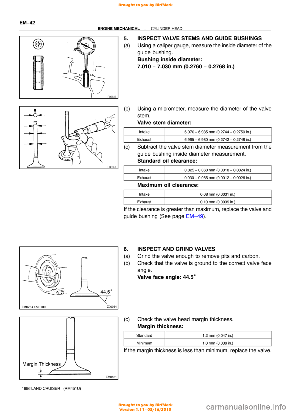
5. INSPECT VALVE STEMS AND GUIDE BUSHINGS
(a) Using a cali per gauge, measure the inside diameter of the
guide bushing.
Bushing inside diameter:
7.010 − 7.030 mm (0.2760 − 0.2768 in.)
(b) Using a micrometer, measure the diameter of the valve stem.
Valve stem diameter:
Intake6.970 − 6.985 mm (0.2744 − 0.2750 in.)
Exhaust6.965 − 6.980 mm (0.2742 − 0.2748 in.)
(c) Subtract the valve stem diameter measurement from the
guide bushing inside diameter measurement.
Standard oil clearance:
Intake0.025 − 0.060 mm (0.0010 − 0.0024 in.)
Exhaust0.030 − 0.065 mm (0.0012 − 0.0026 in.)
Maximum oil clearance:
Intake0.08 mm (0.0031 in.)
Exhaust0.10 mm (0.0039 in.)
If the clearance is greater than maximum, replace the valve and
guide bushing (See page EM−49).
6. INSPECT AND GRIND VALVES
(a) Grind the valve enough to remove pits and carbon.
(b) Check that the valve is ground to the correct valve face angle.
Valve face angle: 44.5°
(c) Check the valve head margin thickness. Margin thickness:
Standard1.2 mm (0.047 in.)
Minimum1.0 mm (0.039 in.)
If the margin thickness is less than minimum, replace the valve.
Brought to you by BirfMark
Brought to you by BirfMark
Version 1.11 - 03/16/2010
Page 828 of 1399

P03849
Overall Length
EM0255
P04415
−
ENGINE MECHANICAL CYLINDER HEAD
EM−43
1996 LAND CRUISER (RM451U)
(d) Check the valve overall length.
Standard overall length:
Intake98.4 mm (3.874 in.)
Exhaust97.4 mm (3.854 in.)
Minimum overall length:
Intake97.9 mm (3.854 in.)
Exhaust97.4 mm (3.835 in.)
If the overall length is less than minimum, replace the valve.
(e) Check the surface of the valve stem tip for wear.
If the valve stem tip is worn, resurface the tip with a grinder or
replace the valve.
NOTICE:
Do not grind off more than minimum.
7. INSPECT AND CLEAN VALVE SEATS
(a) Using a 45° carbide cutter, resurface the valve seats.
Remove only enough metal to clean the seats.
(b) Check the valve seating position. Apply a light coat of prussian blue (or white lead) to the
valve face. Lightly press the valve against the seat. Do not
rotate valve.
(c) Check the valve face and seat for the following:
�If blue appears 360 ° around the face, the valve is
concentric. If not, replace the valve.
�If blue appears 360 ° around the valve seat, the
guide and face are concentric. If not, resurface the
seat.
�Check that the seat contact is in the middle of the
valve face with these width:
Intake1.2 − 1.6 mm (0.047 − 0.063 in.)
Exhaust1.0 − 1.4 mm (0.039 − 0.055 in.)
Brought to you by BirfMark
Brought to you by BirfMark
Version 1.11 - 03/16/2010