Page 275 of 1399
BO48M−01
BO5153
−
BODY BODY OUTSIDE MOULDING
BO−35
1996 LAND CRUISER (RM451U)
REMOVAL
1. REMOVE ROOF DRIP MOULDING
Using SST, pull off the roof drip moulding from front ends.
SST 09806−30010
2. REMOVE FRONT DOOR BELT MOULDING (See page BO−9)
3. REMOVE REAR DOOR BELT MOULDING (See page
BO−15 )
4. REMOVE QUARTER BELT MOULDING
Pry out the clips from the edge of the panel, and remove the
moulding.
Brought to you by BirfMark
Brought to you by BirfMark
Version 1.11 - 03/16/2010
Page 277 of 1399
BO48O−01
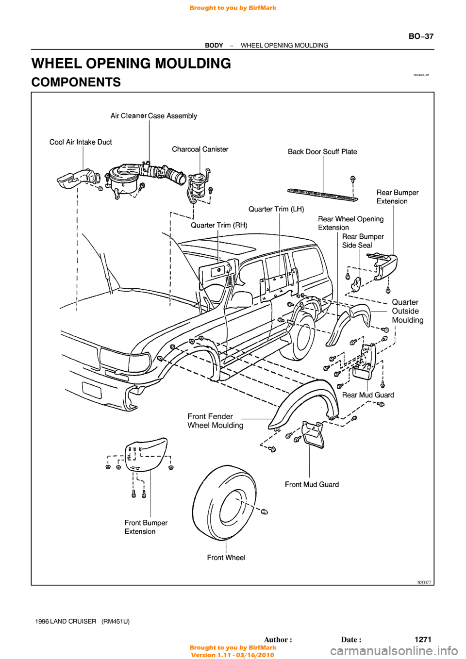
Front Fender
Wheel Moulding
Quarter
Outside
Moulding
−
BODY WHEEL OPENING MOULDING
BO−37
1271
Author�: Date�:
1996 LAND CRUISER (RM451U)
WHEEL OPENING MOULDING
COMPONENTS
Brought to you by BirfMark
Brought to you by BirfMark
Version 1.11 - 03/16/2010
Page 278 of 1399
BO48P−01
N14081
N14075
BO−38
−
BODY WHEEL OPENING MOULDING
1996 LAND CRUISER (RM451U)
REMOVAL
1. REMOVE FRONT FENDER WHEEL OPENING MOULDING
(a) Remove the charcoal canister.
(b) Remove the air cleaner case assembly.
(c) Remove the cool air intake duct.
(d) Remove the front wheel.
(e) Remove the front mudguard.
(f) Remove the front bumper extension.
(g) Remove the 4 nuts from engine room inside service hole.
(h) Remove the 2 screws.
(i) Remove the front wheel opening extension.
2. REAR DOOR SIDE: REMOVE REAR WHEEL OPENING MOULDING
Remove the 2 bolts and moulding.
3. REMOVE REAR WHEEL OPENING MOULDING
(a) Remove the mud guard, bumper extention and back door
scuff plate.
Brought to you by BirfMark
Brought to you by BirfMark
Version 1.11 - 03/16/2010
Page 286 of 1399
BO38Q−01
BO−46
−
BODY WINDSHIELD
1996 LAND CRUISER (RM451U)
REMOVAL
1. REMOVE HOOD
2. REMOVE WIPER ARMS
3. REMOVE COWL LOUVER
4. REMOVE INNER REAR VIEW MIRROR
5. REMOVE PERSONAL LIGHT ASSEMBLY
6. REMOVE PERSONAL LIGHT COVER
7. REMOVE SUN VISORS AND HOLDERS
8. REMOVE ASSIST GRIPS
9. REMOVE FRONT PILLAR GARNISHES
10. LOOSEN ROOF HEADLINING
11. REMOVE WINDSHIELD GLASS
(a) From the outside of the vehicle , cut off the weatherstrip.
NOTICE:
Do not damage the body and the glass.
(b) Push piano wire through between the body and glass from the interior.
(c) Tie both wire ends to the wooden blocks or equivalent.
NOTICE:
When separating, take care not to damage the paint or inte-
rior ornaments.
To prevent scratching the safety pad when removing the
windshield, place a plastic sheet between the piano wire
and safety pad.
(d) Cut the adhesive by pulling the piano wire around it.
(e) Remove the glass.
Brought to you by BirfMark
Brought to you by BirfMark
Version 1.11 - 03/16/2010
Page 308 of 1399
BO5152
BO391−01
BO−68
−
BODY SLIDING ROOF
1996 LAND CRUISER (RM451U)
INSPECTION
1. INSPECT SLIDING ROOF GLASS ALIGNMENT
(a) Start the engine and check the operation time of the slid-
ing roof.
Operation time: Approx. 5 sec.
(b) Check for abnormal noise or binding during operation.
(c) With the sliding roof fully closed, check for water leakage.
(d) Check for a difference in level between the sliding roof weatherstrip and roof panel.
Front End0.9 − 3.9 mm (0.035 − 0.154 in.)
Rear End0.9 − 3.9 mm (0.035 − 0.154 in.)
2. If the sliding roof does not operate:
ADJUST SLIDING ROOF GLASS ALIGNMENT
(a) Remove the control switch cover.
(b) Remove the large screw inside.
NOTICE:
Be careful not to lose the spring washer or shim.
(c) Manually operate the moon roof by inserting a special
crank−shaped screwdriver into the hole and turning the
drive shaft.
Brought to you by BirfMark
Brought to you by BirfMark
Version 1.11 - 03/16/2010
Page 333 of 1399

−
BODY SEAT BELT
BO−93
1996 LAND CRUISER (RM451U)
SEAT BELT
INSPECTION
CAUTION:
Replace the seat belt assembly")
BO0632
BO39M−01
BO0633
15°
45°
N10070
Full Belt Length
minus 200 mm
(7.87 in.)
−
BODY SEAT BELT
BO−93
1996 LAND CRUISER (RM451U)
SEAT BELT
INSPECTION
CAUTION:
Replace the seat belt assembly (outer belt, inner belt, bolts,
nuts or sill −bar) if it has been used in a severe impact. The
entire assembly should be replaced even if damage is not
obvious.
1. All seat belts: RUNNING TEST (IN SAFE AREA)
(a) Fasten the front seat belts.
(b) Drive the car at 10 mph (16 km/h) and make a very hard stop.
Check that the belt locks and cannot be extended at this
time.
HINT:
Conduct this test in a safe area. If the belt does not lock, remove
the belt mechanism assembly and conduct the following static
check. Also, whenever installing a new belt assembly, verify the
proper operation before installation.
2. Driver ’s seat belt (ELR): STATIC TEST
(a) Make sure that the belt locks when pulled out quickly.
(b) Remove the locking retractor assembly.
(c) Tilt the retractor slowly.
(d) Make sure that the belt can be pulled out at a tilt of 15 de-
grees or less, and cannot be pulled out at over 45 degrees
of tilt.
If a problem is found, replace the assembly.
3. Except driver’s seat belt (ALR/ELR):
STATIC TEST
(a) Make sure that the belt locks when pulled out quickly.
(b) Remove the locking retractor assembly.
(c) Pull out the whole belt and measure the length of the whole belt.
Then retract the belt slightly and pull it out again.
(d) Make sure that the belt cannot be extended further.
If a problem is found, replace the assembly.
(e) Retract the whole belt, then pull it out to the full length mi-
nus 200 mm (7.87 in.).
(f) Tilt the retractor slowly.
(g) Make sure that the belt can be pulled out at a tilt of 15 de-
grees or less, and cannot be pulled out at over 45 degrees
of tilt.
If a problem is found, replace the assembly.
Brought to you by BirfMark
Brought to you by BirfMark
Version 1.11 - 03/16/2010
Page 373 of 1399
BR1D8−04
BR−40
−
BRAKE PARKING BRAKE
1996 LAND CRUISER (RM451U)
DISASSEMBLY
1. REMOVE REAR WHEEL
2. REMOVE REAR DISC BRAKE ASSEMBLY
(a) Remove the 2 mounting bolts and remove the disc brake assembly.
Torque: 88 N·m (900 kgf·cm, 65 ft·lbf)
(b) Suspend the disc brake assembly securely. Ensure that the hose is not stretched.
3. REMOVE DISC
Place the matchmarks on the disc and rear hub, and remove the
disc.
HINT:
If the disc cannot be removed easily, turn the shoe adjuster until
the wheel turns freely.
4. REMOVE TENSION SPRING
Using needle −nose pliers, remove the tension spring.
5. REMOVE SHOE RETURN SPRINGS
Using SST, remove the shoe return springs. SST 09717−20010
HINT:
Using SST, install the front shoe return spring and then install
the rear return spring. SST 09718−20010
6. REMOVE SHOE STRUT WITH SPRING
Brought to you by BirfMark
Brought to you by BirfMark
Version 1.11 - 03/16/2010
Page 395 of 1399

INSPECTION
1. INSPECT SPEED SENSOR
(a) Disconnect the speed sensor connector.
(b) Measur")
R05035
BR1NR−01
Z04921
W00552
R13587
R04759
BR−62
−
BRAKE FRONT SPEED SENSOR
1996 LAND CRUISER (RM451U)
INSPECTION
1. INSPECT SPEED SENSOR
(a) Disconnect the speed sensor connector.
(b) Measure the resistance between terminals FR+ and FR −,
and FL+ and FL−.
Resistance: 0.5 − 1.6 kΩ
If resistance value is not specified, replace the sensor.
(c) Check there is no continuity between each terminal and sensor body.
If there is continuity, replace the sensor.
(d) Connect the speed sensor connector.
2. INSPECT SENSOR INSTALLATION
Check the sensor installation bolt is tightened properly and
there is no clearance between the sensor and axle end.
If not, tighten the bolt. Torque: 18 N·m (185 kgf·cm, 13 ft·lbf)
3. VISUALLY INSPECT SENSOR ROTOR SERRATIONS
(a) Remove the axle hub with disc (See page SA−67).
(b) Inspect the sensor rotor serrations for scratches, cracks,
warping or missing teeth.
(c) Install the axle hub with disc SA−9 ).
NOTICE:
To prevent damage to the serrations, do not strike the axle
hub.
Brought to you by BirfMark
Brought to you by BirfMark
Version 1.11 - 03/16/2010

REMOVAL
1. REMOVE ROOF DRIP MOULDING
Using SST, pull off the roof drip moulding from front ends.
SST 09806−30010")

REMOVAL
1. REMOVE FRONT FENDER WHEEL OPENING MOULDING
(a) Remove the charcoal canister.
(b) Remove the air")

REMOVAL
1. REMOVE HOOD
2. REMOVE WIPER ARMS
3. REMOVE COWL LOUVER
4. REMOVE INNER REAR VIEW MIRROR
5. REMOVE PERSONAL LIGHT ASSEMBLY")

INSPECTION
1. INSPECT SLIDING ROOF GLASS ALIGNMENT
(a) Start the engine and check the operation time of the slid-
ing roof")

DISASSEMBLY
1. REMOVE REAR WHEEL
2. REMOVE REAR DISC BRAKE ASSEMBLY
(a) Remove the 2 mounting bolts and remove the disc brake as")