Page 870 of 1399
−
ENGINE MECHANICAL CYLINDER BLOCK
EM−85
1996 LAND CRUISER (RM451U)
14. REMOVE CONNECTING ROD CAPS AND CHECK OIL
CLEARANCE
(a) Check the matchmarks on the connecting rod cap and
connecting rod to ensure correct reassembly.
(b) Remove the connecting rod cap nuts.
(c) Using a plastic− faced hammer, lightly tap the connecting
rod bolts and lift off the connecting rod cap.
HINT:
Keep the lower bearing inserted with the connecting rod cap.
(d) Cover the connecting rod bolts with a short piece of hose to protect the crankshaft from damage.
(e) Clean the crank pin and bearing.
(f) Check the crank pin and bearing for pitting and scratches.
If the crank pin or bearing is damaged, replace the bearings. If
necessary, grind or replace the crankshaft.
(g) Lay a strip of Plastigage across the crank pin.
Brought to you by BirfMark
Brought to you by BirfMark
Version 1.11 - 03/16/2010
Page 871 of 1399

EXAMPLE: Connecting rod ”3” + Crankshaft ”1”= Total number 4 (Use bearing ”4”)
Number marked
Connecting rod
Crankshaft
Use bearing 123
2
2 22
3
3 3
3 3
4445 56
111
EM−86
−
ENGINE MECHANICAL CYLINDER BLOCK
1996 LAND CRUISER (RM451U)
(h) Install the connecting rod cap with the 2 nuts (See page EM−103 ).
NOTICE:
Do not turn the crankshaft.
(i) Remove the 2 nuts and connecting rod cap (See proce-
dure (b) and (c) above).
(j) Measure the Plastigage at its widest point. Standard oil clearance:
STD0.032 − 0.050 mm (0.0013 − 0.0020 in.)
U/S 0.250.033 − 0.073 mm (0.0013 − 0.0029 in.)
Maximum oil clearance: 0.10 mm (0.0039 in.)
If the oil clearance is greater than maximum, replace the bear-
ings. If necessary, grind or replace the crankshaft.
HINT:
If using a standard bearing, replace with one having the same
number. If the number of the bearing cannot be determined, se-
lect the correct bearing by adding together the numbers im-
printed on the connecting rod and crankshaft, then selecting
the bearing with the same number as the total. There are 5 sizes
of standard bearings, marked ”2”, ”3”, ”4”, ”5” and ”6” according-
ly.
Reference
Connecting rod big end inside diameter:
Mark ”1”60.526 − 60.532 mm (2.3829 − 2.3831 in.)
Mark ”2”60.532 − 60.538 mm (2.3831 − 2.3834 in.)
Mark ”3”60.538 − 60.544 mm (2.3834 − 2.3836 in.)
Crankshaft crank pin diameter:
Mark ”1”56.994 − 57.000 mm (2.2439 − 2.2441 in.)
Mark ”2”56.988 − 56.994 mm (2.2436 − 2.2439 in.)
Mark ”3”56.982 − 56.988 mm (2.2434 − 2.2436 in.)
Brought to you by BirfMark
Brought to you by BirfMark
Version 1.11 - 03/16/2010
Page 872 of 1399

P04620
−
ENGINE MECHANICAL CYLINDER BLOCK
EM−87
1996 LAND CRUISER (RM451U)
Standard sized bearing center wall thickness:
Mark ”2”1.744 − 1.747 mm (0.0687 − 0.0688 in.)
Mark ”3”1.747 − 1.750 mm (0.0688 − 0.0689 in.)
Mark ”4”1.750 − 1.753 mm (0.0689 − 0.0690 in.)
Mark ”5”1.753 − 1.756 mm (0.0690 − 0.0691 in.)
Mark ”6”1.756 − 1.759 mm (0.0691 − 0.0693 in.)
(k) Completely remove the Plastigage.
15. R E M O V E P I S TO N A N D C O N N E C T I N G R O D A S-
SEMBLIES
(a) Using a ridge reamer, remove the all carbon from the top of the cylinder.
(b) Push the piston, connecting rod assembly and upper bearing through the top of the cylinder block.
HINT:
�Keep the bearings, connecting rod and cap together.
�Arrange the piston and connecting rod assemblies in cor-
rect order.
16. CHECK CRANKSHAFT THRUST CLEARANCE
Using a dial indicator, measure the thrust clearance while prying
the crankshaft back and forth with a screwdriver. Standard thrust clearance:
0.020 − 0.220 mm (0.0008 − 0.0087 in.)
Maximum thrust clearance: 0.30 mm (0.0118 in.)
If the thrust clearance is greater than maximum, replace the
thrust washers as a set. Thrust washer thickness:
STD2.440 − 2.490 mm (0.0961 − 0.0980 in.)
O/S 0.1252.503 − 2.553 mm (0.0985 − 0.1005 in.)
O/S 0.2502.565 − 2.615 mm (0.1010 − 0.1030 in.)
17. REMOVE MAIN BEARING CAPS AND CHECK OIL
CLEARANCE
(a) Uniformly loosen and remove the main bearing cap bolts
in several passes, in the sequence shown.
Brought to you by BirfMark
Brought to you by BirfMark
Version 1.11 - 03/16/2010
Page 876 of 1399
P03870
−
ENGINE MECHANICAL CYLINDER BLOCK
EM−91
1996 LAND CRUISER (RM451U)
23. DISCONNECT CONNECTING ROD FROM PISTON
(a) Using a small screwdriver, pry out the 2 snap rings.
(b) Gradually heat the piston to 80 − 90°C (176 − 194° F).
(c) Using plastic −faced hammer and brass bar, lightly tap out
the piston pin and remove the connecting rod.
HINT:
�The piston and pin are a matched set.
�Arrange the pistons, pins, rings, connecting rods and
bearings in correct order.
Brought to you by BirfMark
Brought to you by BirfMark
Version 1.11 - 03/16/2010
Page 879 of 1399
EM−94
−
ENGINE MECHANICAL CYLINDER BLOCK
1996 LAND CRUISER (RM451U)
3. INSPECT BEARING OF OIL PUMP DRIVE SHAFT
GEAR
Check the bearing for pitting and scratches.
If the bearing is damaged, replace the cylinder block.
4. CLEAN PISTON
(a) Using a gasket scraper, remove the carbon from the pis-
ton top.
(b) Using a groove cleaning tool or broken ring, clean the pis-
ton ring grooves.
(c) Using solvent and a brush, thoroughly clean the piston.
NOTICE:
Do not use a wire brush.
5. INSPECT PISTON AND CONNECTING ROD
(a) Inspect the piston oil clearance.
HINT:
There are 3 sizes of the standard piston diameter , marked ”1”,
”2” and ”3”. The mark is stamped on the piston top.
Brought to you by BirfMark
Brought to you by BirfMark
Version 1.11 - 03/16/2010
Page 882 of 1399
P03828
P03868
EM0227
−
ENGINE MECHANICAL CYLINDER BLOCK
EM−97
1996 LAND CRUISER (RM451U)
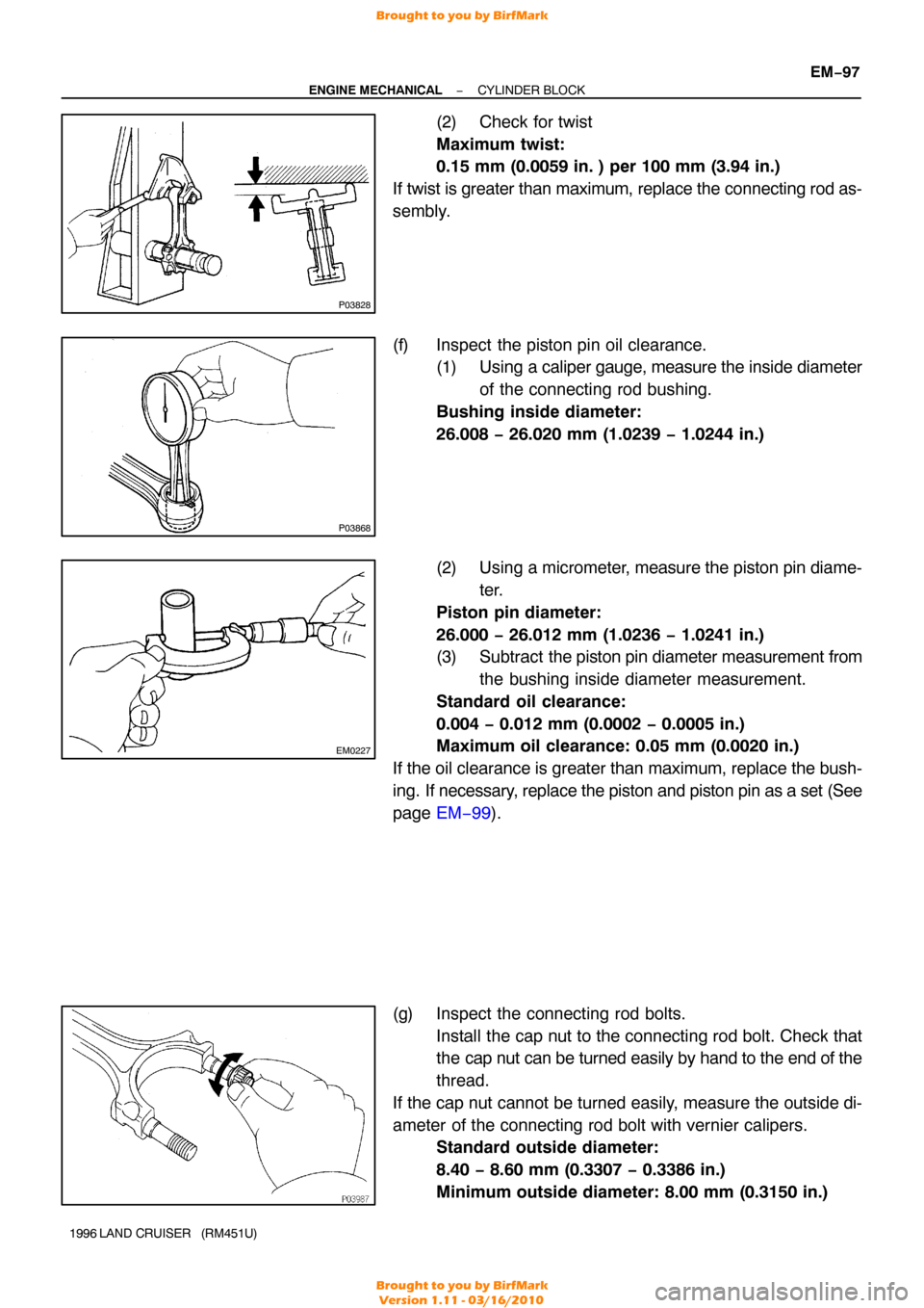
(2) Check for twist
Maximum twist:
0.15 mm (0.0059 in. ) per 100 mm (3.94 in.)
If twist is greater than maximum, replace the connecting rod as-
sembly.
(f) Inspect the piston pin oil clearance. (1) Using a caliper gauge, measure the inside diameter
of the connecting rod bushing.
Bushing inside diameter:
26.008 − 26.020 mm (1.0239 − 1.0244 in.)
(2) Using a micrometer, measure the piston pin diame-
ter.
Piston pin diameter:
26.000 − 26.012 mm (1.0236 − 1.0241 in.)
(3) Subtract the piston pin diameter measurement from
the bushing inside diameter measurement.
Standard oil clearance:
0.004 − 0.012 mm (0.0002 − 0.0005 in.)
Maximum oil clearance: 0.05 mm (0.0020 in.)
If the oil clearance is greater than maximum, replace the bush-
ing. If necessary, replace the piston and piston pin as a set (See
page EM−99 ).
(g) Inspect the connecting rod bolts. Install the cap nut to the connecting rod bolt. Check that
the cap nut can be turned easily by hand to the end of the
thread.
If the cap nut cannot be turned easily, measure the outside di-
ameter of the connecting rod bolt with vernier calipers. Standard outside diameter:
8.40 − 8.60 mm (0.3307 − 0.3386 in.)
Minimum outside diameter: 8.00 mm (0.3150 in.)
Brought to you by BirfMark
Brought to you by BirfMark
Version 1.11 - 03/16/2010
Page 884 of 1399
EM1EI−02
P03827
P03867
−
ENGINE MECHANICAL CYLINDER BLOCK
EM−99
1996 LAND CRUISER (RM451U)
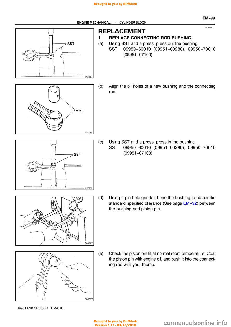
REPLACEMENT
1. REPLACE CONNECTING ROD BUSHING
(a) Using SST and a press, press out the bushing.
SST 09950 −60010 (09951 −00280), 09950 −70010
(09951 −07100)
(b) Align the oil holes of a new bushing and the connecting rod.
(c) Using SST and a press, press in the bushing. SST 09950 −60010 (09951 −00280), 09950 −70010
(09951 −07100)
(d) Using a pin hole grinder, hone the bushing to obtain the standard specified cliarance (See page EM−92) between
the bushing and piston pin.
(e) Check the piston pin fit at normal room temperature. Coat
the piston pin with engine oil, and push it into the connect-
ing rod with your thumb.
Brought to you by BirfMark
Brought to you by BirfMark
Version 1.11 - 03/16/2010
Page 888 of 1399
EM1EJ−01
P04409
−
ENGINE MECHANICAL CYLINDER BLOCK
EM−103
1996 LAND CRUISER (RM451U)
REASSEMBLY
HINT:
�Thoroughly clean all parts to be assembled.
�Before installing the parts, apply new engine oil to all sli-
dining and rotating surfaces.
�Replace all gaskets, O−rings and oil seals with new parts.
1. ASSEMBLE PISTON AND CONNECTING ROD
(a) Install a new snap ring on one side of the piston pin hole.
(b) Gradually heat the piston to 80 − 90° C (176 − 194°F).
(c) Coat the piston pin with engine oil.
(d) Align the front marks of the piston and connecting rod, and push in the piston pin with your thumb.
(e) Install a new snap ring on the other side of the piston pin hole.
2. INSTALL PISTON RINGS
(a) Install the oil ring expander and 2 side rails by hand.
(b) Using a piston ring expander, install the 2 compression rings with the code mark facing upward.
Code mark:
No. 11R
No. 22R
Brought to you by BirfMark
Brought to you by BirfMark
Version 1.11 - 03/16/2010