Page 889 of 1399
EM−104
−
ENGINE MECHANICAL CYLINDER BLOCK
1996 LAND CRUISER (RM451U)
(c) Position the piston rings so that the ring ends are as shown.
NOTICE:
Do not align the ring ends.
3. INSTALL BEARINGS
(a) Align the bearing claw with the groove of the connecting
rod or connecting rod cap.
(b) Install the bearings in the connecting rod and connecting rod cap.
4. INSTALL CYLINDER BLOCK ORIFICE
5. INSTALL OIL NOZZLES AND CHECK VALVES
(a) Align the pin of the oil nozzle with the pin hole of the cylin-
der block.
(b) Install the oil nozzle with the check valve. Install the 6 oil nozzles and check valves.
Torque: 25 N·m (250 kgf·cm, 18 ft·lbf)
Brought to you by BirfMark
Brought to you by BirfMark
Version 1.11 - 03/16/2010
Page 891 of 1399

EM−106
−
ENGINE MECHANICAL CYLINDER BLOCK
1996 LAND CRUISER (RM451U)
(2) Install the 7 main bearing caps in their proper loca-
tions.
HINT:
Each bearing cap has a number and front mark.
(b) Install the main bearing cap bolts.
HINT:
�The main bearing cap bolts are tightened in 2 progressive
steps (steps (b) and (d)).
�If any of the main bearing cap bolts is broken or deformed,
replace it.
(1) Apply a light coat of engine oil on the threads and
under the heads of the main bearings cap bolts.
(2) Install and uniformly tighten the 14 bolts of the main
bearing caps, in several passes, in the sequence
shown.
Torque: 74 N·m (750 kgf·cm, 54 ft·lbf)
If any one of the main bearing cap bolts does not meet the
torque specification, replace the main bearing cap bolt.
(3) Mark the front of the main bearing cap bolt withpaint.
(4) Retighten the main bearing cap bolts by 90 ° in the
numerical order shown above.
(5) Check that the painted mark is now at a 90° angle
to the front.
(c) Check that the crankshaft turns smoothly.
(d) Check that the crankshaft thrust clearance (See page EM−83 ).
10. INSTALL PISTON AND CONNECTING ROD AS- SEMBLIES
(a) Cover the connecting rod bolts with a short piece of hose
to protect the crankshaft from damage.
Brought to you by BirfMark
Brought to you by BirfMark
Version 1.11 - 03/16/2010
Page 892 of 1399
−
ENGINE MECHANICAL CYLINDER BLOCK
EM−107
1996 LAND CRUISER (RM451U)
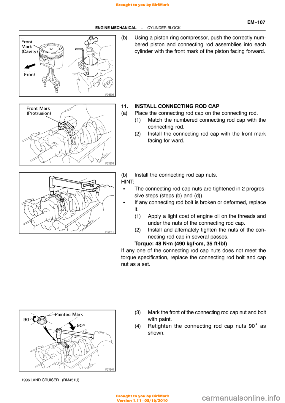
(b) Using a piston ring compressor, push the correctly num-
bered piston and connecting rod assemblies into each
cylinder with the front mark of the piston facing forward.
11. INSTALL CONNECTING ROD CAP
(a) Place the connecting rod cap on the connecting rod. (1) Match the numbered connecting rod cap with theconnecting rod.
(2) Install the connecting rod cap with the front mark facing for ward.
(b) Install the connecting rod cap nuts.
HINT:
�The connecting rod cap nuts are tightened in 2 progres-
sive steps (steps (b) and (d)).
�If any connecting rod bolt is broken or deformed, replace
it.
(1) Apply a light coat of engine oil on the threads and under the nuts of the connecting rod cap.
(2) Install and alternately tighten the nuts of the con-
necting rod cap in several passes.
Torque: 48 N·m (490 kgf·cm, 35 ft·lbf)
If any one of the connecting rod cap nuts does not meet the
torque specification, replace the connecting rod bolt and cap
nut as a set.
(3) Mark the front of the connecting rod cap nut and bolt
with paint.
(4) Retighten the connecting rod cap nuts 90 ° as
shown.
Brought to you by BirfMark
Brought to you by BirfMark
Version 1.11 - 03/16/2010
Page 893 of 1399
P04615
EM−108
−
ENGINE MECHANICAL CYLINDER BLOCK
1996 LAND CRUISER (RM451U)
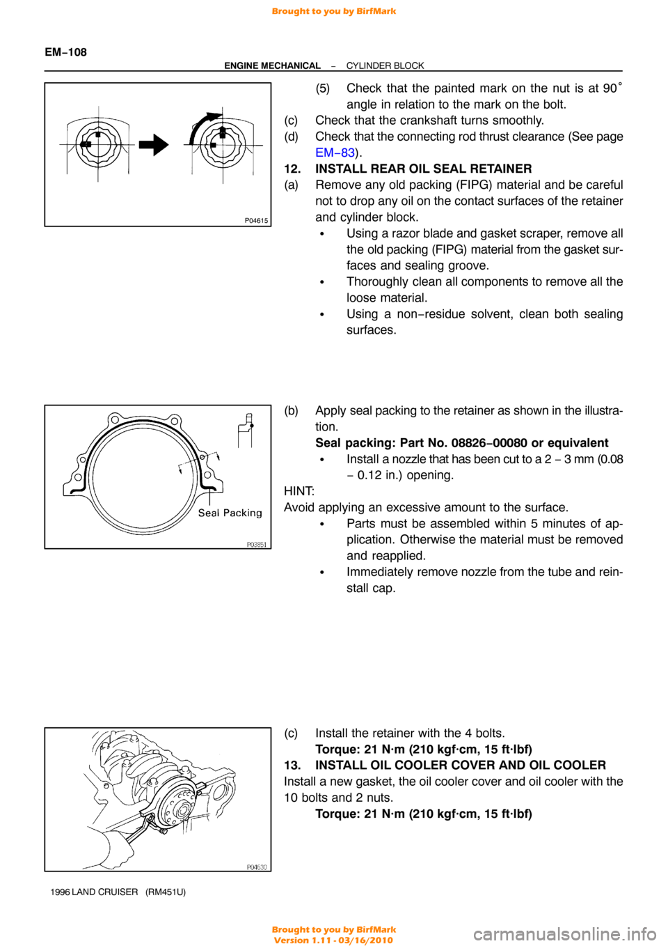
(5) Check that the painted mark on the nut is at 90 °
angle in relation to the mark on the bolt.
(c) Check that the crankshaft turns smoothly.
(d) Check that the connecting rod thrust clearance (See page
EM−83 ).
12. INSTALL REAR OIL SEAL RETAINER
(a) Remove any old packing (FIPG) material and be careful not to drop any oil on the contact surfaces of the retainer
and cylinder block.
�Using a razor blade and gasket scraper, remove all
the old packing (FIPG) material from the gasket sur-
faces and sealing groove.
�Thoroughly clean all components to remove all the
loose material.
�Using a non −residue solvent, clean both sealing
surfaces.
(b) Apply seal packing to the retainer as shown in the illustra-
tion.
Seal packing: Part No. 08826−00080 or equivalent
�Install a nozzle that has been cut to a 2 − 3 mm (0.08
− 0.12 in.) opening.
HINT:
Avoid applying an excessive amount to the surface.
�Parts must be assembled within 5 minutes of ap-
plication. Otherwise the material must be removed
and reapplied.
�Immediately remove nozzle from the tube and rein-
stall cap.
(c) Install the retainer with the 4 bolts. Torque: 21 N·m (210 kgf·cm, 15 ft·lbf)
13. INSTALL OIL COOLER COVER AND OIL COOLER
Install a new gasket, the oil cooler cover and oil cooler with the
10 bolts and 2 nuts. Torque: 21 N·m (210 kgf·cm, 15 ft·lbf)
Brought to you by BirfMark
Brought to you by BirfMark
Version 1.11 - 03/16/2010
Page 945 of 1399
PP−4
−
PREPARATION ENGINE MECHANICAL
53
Author�: Date�:
1996 LAND CRUISER (RM451U)
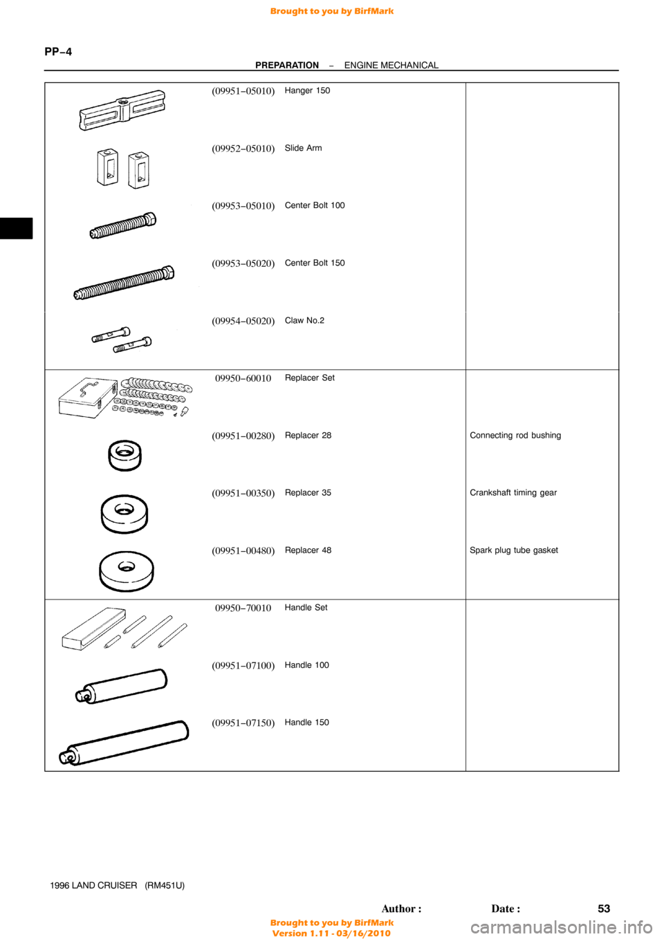
(09951−05010)Hanger 150
(09952−05010)Slide Arm
(09953−05010)Center Bolt 100
(09953−05020)Center Bolt 150
(09954−05020)Claw No.2
09950−60010Replacer Set
(09951−00280)Replacer 28Connecting rod bushing
(09951−00350)Replacer 35Crankshaft timing gear
(09951−00480)Replacer 48Spark plug tube gasket
09950−70010Handle Set
(09951−07100)Handle 100
(09951−07150)Handle 150
Brought to you by BirfMark
Brought to you by BirfMark
Version 1.11 - 03/16/2010
Page 947 of 1399
PP302-01
PP-6
-
PREPARATION ENGINE MECHANICAL
1996 LAND CRUISER (RM451U)
EQUIPMENT
Caliper gauge
CO/HC meter
Compression gauge
Connecting rod aligner
Cylinder gauge
Dial indicator
Dye penetrant
Engine tune-up tester
Heater
Magnetic finger
Micrometer
OBD II scan toolEngine speed
Piston ring compressor
Piston ring expander
Plastigage
Precision straight edge
Soft brush
Spring testerValve spring
Steel squareValve spring
Thermometer
Torque wrench
Valve seat cutter
Vernier calipers
Brought to you by BirfMark
Brought to you by BirfMark
Version 1.11 - 03/16/2010
Page 1090 of 1399
SA1UM−03
FA2038
−
SUSPENSION AND AXLE FRONT DIFFERENTIAL CARRIER
SA−27
1996 LAND CRUISER (RM451U)
REMOVAL
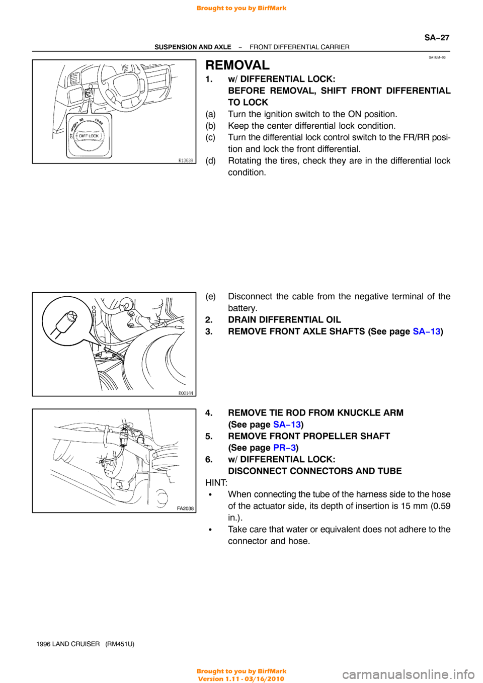
1. w/ DIFFERENTIAL LOCK:
BEFORE REMOVAL, SHIFT FRONT DIFFERENTIAL
TO LOCK
(a) Turn the ignition switch to the ON position.
(b) Keep the center differential lock condition.
(c) Turn the differential lock control switch to the FR/RR posi-
tion and lock the front differential.
(d) Rotating the tires, check they are in the differential lock condition.
(e) Disconnect the cable from the negative terminal of the battery.
2. DRAIN DIFFERENTIAL OIL
3. REMOVE FRONT AXLE SHAFTS (See page SA−13)
4. REMOVE TIE ROD FROM KNUCKLE ARM (See page SA−13 )
5. REMOVE FRONT PROPELLER SHAFT (See page PR−3 )
6. w/ DIFFERENTIAL LOCK: DISCONNECT CONNECTORS AND TUBE
HINT:
�When connecting the tube of the harness side to the hose
of the actuator side, its depth of insertion is 15 mm (0.59
in.).
�Take care that water or equivalent does not adhere to the
connector and hose.
Brought to you by BirfMark
Brought to you by BirfMark
Version 1.11 - 03/16/2010
Page 1300 of 1399
SR16T−01
−
STEERING STEERING LINKAGE
SR−47
1996 LAND CRUISER (RM451U)
INSTALLATION
HINT:
When connecting the ball stud to the arm or rod, remove the
grease on the joint surfaces.
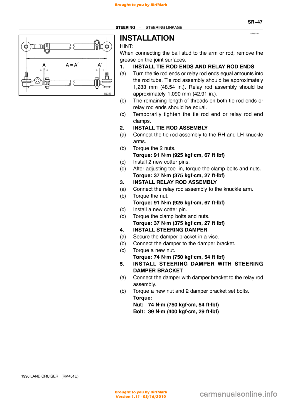
1. INSTALL TIE ROD ENDS AND RELAY ROD ENDS
(a) Turn the tie rod ends or relay rod ends equal amounts into
the rod tube. Tie rod assembly should be approximately
1,233 mm (48.54 in.). Relay rod assembly should be
approximately 1,090 mm (42.91 in.).
(b) The remaining length of threads on both tie rod ends or relay rod ends should be equal.
(c) Temporarily tighten the tie rod end or relay rod end clamps.
2. INSTALL TIE ROD ASSEMBLY
(a) Connect the tie rod assembly to the RH and LH knuckle arms.
(b) Torque the 2 nuts. Torque: 91 N·m (925 kgf·cm, 67 ft·lbf)
(c) Install 2 new cotter pins.
(d) After adjusting toe−in, torque the clamp bolts and nuts. Torque: 37 N·m (375 kgf·cm, 27 ft·lbf)
3. INSTALL RELAY ROD ASSEMBLY
(a) Connect the relay rod assembly to the knuckle arm.
(b) Torque the nut. Torque: 91 N·m (925 kgf·cm, 67 ft·lbf)
(c) Install a new cotter pin.
(d) Torque the clamp bolts and nuts. Torque: 37 N·m (375 kgf·cm, 27 ft·lbf)
4. INSTALL STEERING DAMPER
(a) Secure the damper bracket in a vise.
(b) Connect the damper to the damper bracket.
(c) Torque a new nut. Torque: 74 N·m (750 kgf·cm, 54 ft·lbf)
5. INSTALL STEERING DAMPER WITH STEERING DAMPER BRACKET
(a) Connect the damper with damper bracket to the relay rod
assembly.
(b) Torque a new nut and 2 damper bracket set bolts.
Torque:
Nut: 74 N·m (750 kgf·cm, 54 ft·lbf)
Bolt: 39 N·m (400 kgf·cm, 29 ft·lbf)
Brought to you by BirfMark
Brought to you by BirfMark
Version 1.11 - 03/16/2010