Page 1018 of 1399

REMOVAL
1.")
PR06P−01
Z09285
Matchmarks
Transfer
Front Propeller Shaft
Z09286
Matchmarks
Transfer
Rear Propeller Shaft
−
PROPELLER SHAFT PROPELLER SHAFT ASSEMBLY
PR−3
1996 LAND CRUISER (RM451U)
REMOVAL
1. REMOVE FRONT PROPELLER SHAFT
(a) Place matchmarks on the propeller shaft flange and
transfer.
(b) Remove the 4 nuts and washers. Torque: 74 N·m (750 kgf·cm, 54 ft·lbf)
(c) Place matchmarks on the propeller shaft flange and dif-
ferential.
(d) Remove the 4 nuts, bolts and washers. Torque: 74 N·m (750 kgf·cm, 54 ft·lbf)
(e) Remove the front propeller shaft.
2. REMOVE REAR PROPELLER SHAFT
(a) Place matchmarks on the propeller shaft flange and
transfer.
(b) Remove the 4 nuts and washers. Torque: 88 N·m (900 kgf·cm, 65 ft·lbf)
(c) Place matchmarks on the propeller shaft flange and dif- ferential.
(d) Remove the 4 nuts, bolts and washers. Torque: 88 N·m (900 kgf·cm, 65 ft·lbf)
(e) Remove the rear propeller shaft.
Brought to you by BirfMark
Brought to you by BirfMark
Version 1.11 - 03/16/2010
Page 1055 of 1399

INSTALLATION
NOTICE:
Never use airbag parts from another vehicle. When replac-
ing pa")
RS0PC−03
−
SUPPLEMENTAL RESTRAINT SYSTEM FRONT PASSENGER AIRBAG ASSEMBLY
RS−31
1996 LAND CRUISER (RM451U)
INSTALLATION
NOTICE:
Never use airbag parts from another vehicle. When replac-
ing parts, replace with new parts.
1. INSTALL FRONT PASSENGER AIRBAG ASSEMBLY
Install the airbag door and front passenger airbag assembly to
the instrument panel.
CAUTION:
�Make sure that no foreign objects are trapped be-
tween the airbag and the module.
�Do not damage the strap when installing the module.
If the airbag door is cracked or its surface is peeling,
always replace it with a new airbag door.
NOTICE:
If the front passenger airbag assembly has been dropped,
or there are cracks, dents or other defects in the case or
connector, replace the front passenger airbag assembly
with a new one.
2. INSTALL INSTRUMENT PANEL (See page BO−80)
Install the 2 bolts to instrument panel reinforcement. Torque: 20 N·m (210 kgf·cm, 15 ft·lbf)
NOTICE:
Make sure the front passenger airbag assembly is installed
to the specified torque.When installing the instrument pan-
el, take care that the airbag wire harness does not interfere
with other parts and is not pinched between other parts.
3. CONNECT AIRBAG CONNECTOR
(a) Connect the airbag connector.
(b) Install the airbag connector to the airbag bracket.
(c) Install the glove compartment door.
Brought to you by BirfMark
Brought to you by BirfMark
Version 1.11 - 03/16/2010
Page 1060 of 1399

INSTALLATION
NOTICE:
�Never use SRS parts from another vehicle. When replacing parts, replace")
RS0PF−01
RS−36
−
SUPPLEMENTAL RESTRAINT SYSTEM AIRBAG SENSOR ASSEMBLY
1996 LAND CRUISER (RM451U)
INSTALLATION
NOTICE:
�Never use SRS parts from another vehicle. When replacing parts, replace with \
new parts.
�Never reuse the airbag sensor assembly involved in a collision when the airbag has deployed.
�Never repair a sensor in order to reuse it.
1. INSTALL AIRBAG SENSOR ASSEMBLY
(a) Using a torx wrench, install the airbag sensor assembly with the 4 screw\
s. Torx wrench: T40 (Part No. 09042 −00020 or locally manufactured tool)
Torque: 21 N·m (210 kgf·cm, 15 ft·lbf)
(b) Connect the connector.
NOTICE:
�Installation of the connector is done with the sensor assembly installed\
.
�Make sure the sensor assembly is installed to the specified torque.
�If the sensor assembly has been dropped, or there are cracks, dents or o\
ther defects in the
case, bracket or connector, replace the sensor assembly with a new one.
�When installing the sensor assembly, take care that the SRS wiring does not interfere with other
parts and is not pinched between other parts.
�After installation, shake the sensor assembly to check that there is no \
looseness.
2. INSTALL THE REMOVED PARTS
Brought to you by BirfMark
Brought to you by BirfMark
Version 1.11 - 03/16/2010
Page 1067 of 1399

FRONT WHEEL ALIGNMENT
INSPECTION
1. MEASU")
SA1U9−02
Z03382
SA3213
AB
D
C
Front
R05628
A
B
A = B
SA−4
−
SUSPENSION AND AXLE FRONT WHEEL ALIGNMENT
861
Author�: Date�:
1996 LAND CRUISER (RM451U)
FRONT WHEEL ALIGNMENT
INSPECTION
1. MEASURE VEHICLE HEIGHT
Clearance:
A (Follow spring clearance): 36 mm (1.42 in.)
B (Bumper stopper clearance): 104 mm (4.09 in.)
If the clearance of the vehicle is not standard, try to level the ve-
hicle by rocking it down.
If still not correct, check for bad springs or suspension parts.
2. INSTALL CAMBER−CASTER−KINGPIN GAUGE OR ONTO WHEEL ALIGNMENT TESTER
Follow the specific instructions of the equipment manufacturer.
3. INSPECT CAMBER, CASTER AND STEERING AXIS INCLINATION
Camber
Left−right error1°00’ ± 45
45’ or less
Caster Left−right error3°00’ ± 1°
45’ or less
Steering axis inclination13 °00’ ± 45’
Camber, caster and steering axis inclination are not adjustable.
If measurements are not within the specification, inspect the
suspension parts for damaged and/or worn out parts and re-
place them as necessary.
4. INSPECT TOE −IN
To e−in
(total)A+B: 0.2 ° ± 0.2°
C −D: 2 ± 2 mm (0.08 ± 0.08 in.)
If toe− in is not within the specification, adjust by the tie rod end.
5. ADJUST TOE−IN
(a) Loosen the clamp bolts and nuts.
(b) Adjust toe−in to the correct value by turning the tie rod.
HINT:
Make sure that the lengths of the left and right tie rod ends are
the same.
(c) Torque the clamp bolts and nuts. Torque: 37 N·m (375 kgf·cm, 27 ft·lbf)
Brought to you by BirfMark
Brought to you by BirfMark
Version 1.11 - 03/16/2010
Page 1068 of 1399

HINT:
Th")
R05626
Front
Side+10
° +60
°
−10 °
FA0507
FA0018
A B
Front BA
A: Inside
B: Outside
−
SUSPENSION AND AXLE FRONT WHEEL ALIGNMENT
SA−5
862
Author�: Date�:
1996 LAND CRUISER (RM451U)
HINT:
The clamps opening must be positioned at the rear of the tie rod
end face within 60 °±10° from the vehicle axis.
6. INSPECT WHEEL ANGLE
(a) Remove the caps of the knuckle stopper bolts and check the steering angles.
(b) Turn the steering wheel fully, and measure the turning angle.
Inside wheel32°00’ − 35°00’
Outside wheel31 °00’ (Reference)
HINT:
When the steering wheel is fully turned, make sure that the
wheel is not touching the body or brake flexible hose.
If maximum steering angles differ from the standard value, ad-
just the wheel angle with the knuckle stopper bolts.
Torque: 44 N·m (450 kgf·cm, 33 ft·lbf)
If the wheel angle still cannot be adjusted within limits, inspect
and replace damaged or worn steering parts.
Brought to you by BirfMark
Brought to you by BirfMark
Version 1.11 - 03/16/2010
Page 1072 of 1399

INSTALLATION
1. PACK BEARINGS WITH MP GREASE
(a) Place MP grease on the palm of your hand")
SA1UD−01
SA2636
Grease
R04134
SST
−
SUSPENSION AND AXLE FRONT AXLE HUB
SA−9
1996 LAND CRUISER (RM451U)
INSTALLATION
1. PACK BEARINGS WITH MP GREASE
(a) Place MP grease on the palm of your hand.
(b) Pack grease into the bearing until the grease oozes out
from the other side.
(c) Do the same around the bearing circumference.
2. COAT INSIDE OF HUB WITH MP GREASE
3. INSTALL INNER BEARING AND OIL SEAL
(a) Place the inner bearing into the hub.
(b) Using SST, install a new oil seal into the hub. SST 09950−60020 (09951 −00910),
09950 −70010 (09951 −07150)
(c) Coat the oil seal lip with MP grease.
4. INSTALL AXLE HUB WITH DISC TO SPINDLE
(a) Place the axle hub with disc to the spindle.
(b) Install the outer bearing.
(c) Install the thrust washer.
5. ADJUST PRELOAD
(a) Using SST, torque the adjusting nut.
SST 09607−60020
Torque: 59 N·m (600 kgf·cm, 43 ft·lbf)
(b) Turn the hub right and left 2 or 3 times.
(c) Using SST, torque the adjusting nut.
SST 09607−60020
Torque: 59 N·m (600 kgf·cm, 43 ft·lbf)
(d) Loosen the nut until it can be turned by hand.
(e) Using SST, torque the adjusting nut again.
SST 09607−60020
Torque: 5.4 N·m (55 kgf·cm, 48 in.·lbf)
NOTICE:
Check that the bearing has no play.
(f) Using a spring tension gauge, measure the preload.
Preload (at starting):
28 − 56 N (2.9 − 5.7 kgf, 6.4 − 12.6 lbf)
6. INSTALL LOCK WASHER AND LOCK NUT
(a) Install a new lock washer and lock nut.
(b) Using SST, torque the lock nut. SST 09607−60020
Torque: 64 N·m (650 kgf·cm, 47 ft·lbf)
(c) Check that axle hub turns smoothly and that the bearing has no play.
(d) Using a spring tension gauge, check the preload. Preload (at starting):
28−56 N (2.9−5.7 kgf, 6.4−12.6 lbf)
If it is not within the specification, adjust it with the adjusting nut
after removing the lock washer and lock nut.
Brought to you by BirfMark
Brought to you by BirfMark
Version 1.11 - 03/16/2010
Page 1073 of 1399
R08416
SA−10
−
SUSPENSION AND AXLE FRONT AXLE HUB
1996 LAND CRUISER (RM451U)
(e) Secure the lock nut by bending one of the lock washer
teeth inward and the other lock washer teeth outward.
7. INSTALL FLANGE
(a) Place a new gasket in position on the axle hub.
(b) Apply MP grease to the inner flange splines.
(c) Install the flange to the axle hub.
(d) Install the 6 cone washers, plate washers and nuts.
(e) Torque the 6 nuts.
Torque: 35 N·m (360 kgf·cm, 26 ft·lbf)
(f) Install the bolt in the axle shaft and pull it out.
(g) Using a snap ring expander, install a new snap ring.
(h) Remove the bolt.
(i) Coat inside of the cap with MP grease.
(j) Install the cap to the flange.
8. INSTALL BRAKE CALIPER (See page BR−29 )
9. INSTALL FRONT WHEEL Torque:
Steel wheel: 147 N·m (1,500 kgf·cm, 109 ft·lbf)
Alumimum wheel: 103 N·m (1,050 kgf·cm, 76 ft·lbf)
10. BLEED BRAKE LINE
Brought to you by BirfMark
Brought to you by BirfMark
Version 1.11 - 03/16/2010
Page 1074 of 1399
SA1UE−01
−
SUSPENSION AND AXLE FRONT WHEEL HUB BOLT
SA−11
868
Author�: Date�:
1996 LAND CRUISER (RM451U)
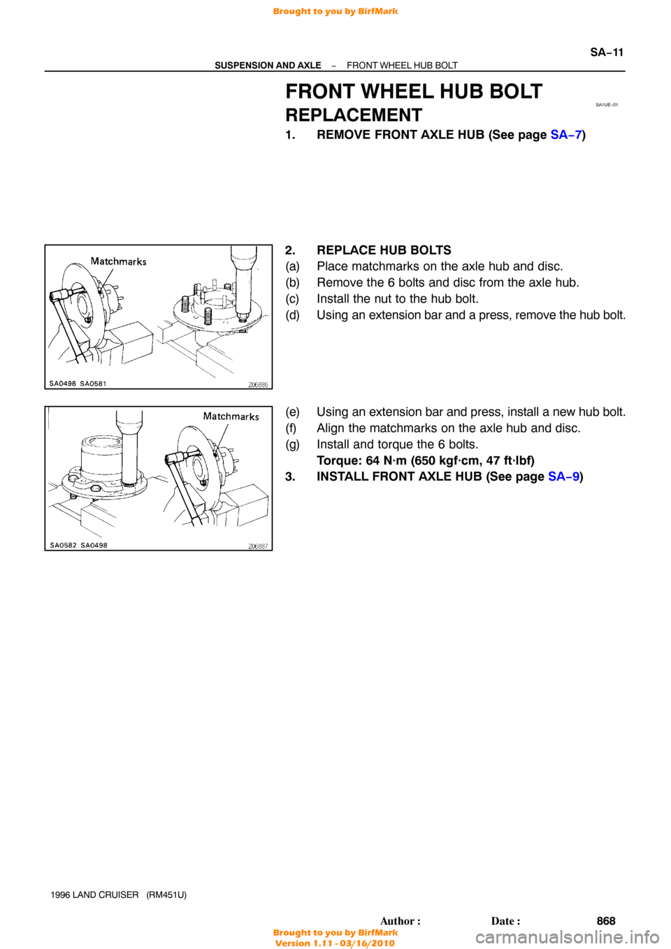
FRONT WHEEL HUB BOLT
REPLACEMENT
1. REMOVE FRONT AXLE HUB (See page SA−7 )
2. REPLACE HUB BOLTS
(a) Place matchmarks on the axle hub and disc.
(b) Remove the 6 bolts and disc from the axle hub.
(c) Install the nut to the hub bolt.
(d) Using an extension bar and a press, remove the hub bolt.
(e) Using an extension bar and press, install a new hub bolt.
(f) Align the matchmarks on the axle hub and disc.
(g) Install and torque the 6 bolts. Torque: 64 N·m (650 kgf·cm, 47 ft·lbf)
3. INSTALL FRONT AXLE HUB (See page SA−9)
Brought to you by BirfMark
Brought to you by BirfMark
Version 1.11 - 03/16/2010

(e) Secure the lock nut by bending one of the lock washer
teeth inward and the other lock washer teeth outward.
7. I")