Page 868 of 1399
EM1Q8−01
−
ENGINE MECHANICAL CYLINDER BLOCK
EM−83
1996 LAND CRUISER (RM451U)
DISASSEMBLY
1. REMOVE DRIVE PLATE
Uniformly loosen and remove the drive plate bolts, in several
passes, in the sequence shown.
2. INSTALL ENGINE TO ENGINE STAND FOR DIS-
ASSEMBLY
3. REMOVE CYLINDER HEAD (See page EM−28 )
4. REMOVE TIMING CHAIN AND GEARS (See page EM−13 )
5. REMOVE OIL FILTER (See page LU−2)
6. REMOVE OIL FILTER UNION
7. REMOVE KNOCK SENSORS
Using SST, remove the 2 knock sensors. SST 09816−30010
8. REMOVE PS PUMP
(a) Remove the 2 nuts and pump.
(b) Remove the O−ring from the pump.
Brought to you by BirfMark
Brought to you by BirfMark
Version 1.11 - 03/16/2010
Page 872 of 1399

Standard sized bearing center wall thickness:
Mark ”2”1.744 − 1.747 mm (0.0687 − 0.0688 in.)
Mark ”3”1.747")
P04620
−
ENGINE MECHANICAL CYLINDER BLOCK
EM−87
1996 LAND CRUISER (RM451U)
Standard sized bearing center wall thickness:
Mark ”2”1.744 − 1.747 mm (0.0687 − 0.0688 in.)
Mark ”3”1.747 − 1.750 mm (0.0688 − 0.0689 in.)
Mark ”4”1.750 − 1.753 mm (0.0689 − 0.0690 in.)
Mark ”5”1.753 − 1.756 mm (0.0690 − 0.0691 in.)
Mark ”6”1.756 − 1.759 mm (0.0691 − 0.0693 in.)
(k) Completely remove the Plastigage.
15. R E M O V E P I S TO N A N D C O N N E C T I N G R O D A S-
SEMBLIES
(a) Using a ridge reamer, remove the all carbon from the top of the cylinder.
(b) Push the piston, connecting rod assembly and upper bearing through the top of the cylinder block.
HINT:
�Keep the bearings, connecting rod and cap together.
�Arrange the piston and connecting rod assemblies in cor-
rect order.
16. CHECK CRANKSHAFT THRUST CLEARANCE
Using a dial indicator, measure the thrust clearance while prying
the crankshaft back and forth with a screwdriver. Standard thrust clearance:
0.020 − 0.220 mm (0.0008 − 0.0087 in.)
Maximum thrust clearance: 0.30 mm (0.0118 in.)
If the thrust clearance is greater than maximum, replace the
thrust washers as a set. Thrust washer thickness:
STD2.440 − 2.490 mm (0.0961 − 0.0980 in.)
O/S 0.1252.503 − 2.553 mm (0.0985 − 0.1005 in.)
O/S 0.2502.565 − 2.615 mm (0.1010 − 0.1030 in.)
17. REMOVE MAIN BEARING CAPS AND CHECK OIL
CLEARANCE
(a) Uniformly loosen and remove the main bearing cap bolts
in several passes, in the sequence shown.
Brought to you by BirfMark
Brought to you by BirfMark
Version 1.11 - 03/16/2010
Page 876 of 1399
P03870
−
ENGINE MECHANICAL CYLINDER BLOCK
EM−91
1996 LAND CRUISER (RM451U)
23. DISCONNECT CONNECTING ROD FROM PISTON
(a) Using a small screwdriver, pry out the 2 snap rings.
(b) Gradually heat the piston to 80 − 90°C (176 − 194° F).
(c) Using plastic −faced hammer and brass bar, lightly tap out
the piston pin and remove the connecting rod.
HINT:
�The piston and pin are a matched set.
�Arrange the pistons, pins, rings, connecting rods and
bearings in correct order.
Brought to you by BirfMark
Brought to you by BirfMark
Version 1.11 - 03/16/2010
Page 879 of 1399
EM−94
−
ENGINE MECHANICAL CYLINDER BLOCK
1996 LAND CRUISER (RM451U)
3. INSPECT BEARING OF OIL PUMP DRIVE SHAFT
GEAR
Check the bearing for pitting and scratches.
If the bearing is damaged, replace the cylinder block.
4. CLEAN PISTON
(a) Using a gasket scraper, remove the carbon from the pis-
ton top.
(b) Using a groove cleaning tool or broken ring, clean the pis-
ton ring grooves.
(c) Using solvent and a brush, thoroughly clean the piston.
NOTICE:
Do not use a wire brush.
5. INSPECT PISTON AND CONNECTING ROD
(a) Inspect the piston oil clearance.
HINT:
There are 3 sizes of the standard piston diameter , marked ”1”,
”2” and ”3”. The mark is stamped on the piston top.
Brought to you by BirfMark
Brought to you by BirfMark
Version 1.11 - 03/16/2010
Page 885 of 1399

2. REPLACE OVERSIZED (O/S) PISTONS FOR CYLIN-
DER BORING
HINT:
�Bore all the 6 cylinders for the O/S pisto")
P04907
P08469
SST
EM−100
−
ENGINE MECHANICAL CYLINDER BLOCK
1996 LAND CRUISER (RM451U)
2. REPLACE OVERSIZED (O/S) PISTONS FOR CYLIN-
DER BORING
HINT:
�Bore all the 6 cylinders for the O/S piston outside diame-
ter.
�Replace all the piston rings with ones to match the O/S
pistons.
(a) Keep 6 new O/S pistons. O/S piston diameter:
O/S 0.50100.450 − 100.480 mm (3.9547 − 3.9559 in.)
O/S 1.00100.950 − 100.980 mm (3.9744 − 3.9756 in.)
(b) Using a micrometer, measure the piston diameter at right
angles to the piston pin center line, 42 mm (1.65 in.) from
the piston head.
(c) Calculate the amount of each cylinder is to be rebored as
follows:
Size to be rebored = P + C − H
P = Piston diameter
C = Piston oil clearance
0.040 − 0.060 mm (0.0016 − 0.0024 in.)
H = Allowance for honing
0.02 mm (0.0008 in.) or less
(d) Bore and hone the cylinders to calculated dimensions. Maximum honing: 0.02 mm (0.0008 in.)
NOTICE:
Excess honing will destroy the finished roundness.
3. REPLACE CRANKSHAFT FRONT OIL SEAL
HINT:
There are 2 methods ((a) and (b)) to replace the oil seal.
(a) If the timing chain cover is removed from the cylinder block:
(1) Using a screwdriver and a hammer, tap out the oilseal.
(2) Using SST and a hammer, tap in a new oil seal until
its surface is flush with the timing chain cover edge.
SST 09316−60011 (09316 −00011, 09316−00051)
(3) Apply MP grease to the oil seal lip.
NOTICE:
Do not let foreign matter get onto the lip of the oil seal.
Brought to you by BirfMark
Brought to you by BirfMark
Version 1.11 - 03/16/2010
Page 886 of 1399

(b) If the timing chain cover is installed to the cylinder block:
(1)")
P05005
P08506
SST
P04518
P04970
SST
P08643
Cut Position
−
ENGINE MECHANICAL CYLINDER BLOCK
EM−101
1996 LAND CRUISER (RM451U)
(b) If the timing chain cover is installed to the cylinder block:
(1) Using a screwdriver, pry out the oil seal.
NOTICE:
Be careful not to damage the crankshaft. Tape the screw-
driver tip.
(2) Apply MP grease to a new oil seal lip.
NOTICE:
Do not let foreign matter get onto the lip of the oil seal.
(3) Using SST and a hammer, tap in the oil seal until its
surface is flush with the timing chain cover edge.
SST 09316−60011 (09316 −00011, 09316−00051)
4. REPLACE CRANKSHAFT REAR OIL SEAL
HINT:
There are 2 methods ((a) and (b)) to replace the oil seal.
(a) If the rear oil seal retainer is removed from the cylinder block:
(1) Using a screwdriver and a hammer, tap out the oil
seal.
(2) Using SST and a hammer, tap in a new oil seal until
its surface is flush with the rear oil seal edge.
SST 09223−15030, 09950 −70010 (09951−07150)
NOTICE:
Do not let foreign matter get onto the lip of the oil seal.
(b) If the rear oil seal retainer is installed to the cylinder block:
(1) Using a knife, cut off the oil seal lip.
(2) Using a screwdriver, pry out the oil seal.
NOTICE:
Be careful not to damage the crankshaft. Tape the screw-
driver tip.
Brought to you by BirfMark
Brought to you by BirfMark
Version 1.11 - 03/16/2010
Page 894 of 1399

14. INSTALL LH ENGINE MOUNTING BRACKET
(a) Install the bracket with the 4 bolts.
Torque: 69 N·m (700 kgf·cm, 51 ft·lbf)
(b")
−
ENGINE MECHANICAL CYLINDER BLOCK
EM−109
1996 LAND CRUISER (RM451U)
14. INSTALL LH ENGINE MOUNTING BRACKET
(a) Install the bracket with the 4 bolts.
Torque: 69 N·m (700 kgf·cm, 51 ft·lbf)
(b) Install the insulator with the nut. Torque: 72 N·m (730 kgf·cm, 43 ft·lbf)
15. INSTALL RH ENGINE MOUNTING BRACKET
(a) Install the bracket with the 4 bolts. Torque: 69 N·m (700 kgf·cm, 51 ft·lbf)
(b) Install the insulator with the nut. Torque: 72 N·m (730 kgf·cm, 43 ft·lbf)
16. INSTALL PS PUMP
(a) Place a new O−ring to the pump.
(b) Install the pump with the 2 nuts.
Torque: 36 N·m (370 kgf·cm, 27 ft·lbf)
17. INSTALL KNOCK SENSORS
Using SST, install the 2 knock sensors. SST 09816−30010
Torque: 44 N·m (450 kgf·cm, 33 ft·lbf)
18. INSTALL OIL FILTER UNION
Torque: 44 N·m (450 kgf·cm, 33 ft·lbf)
19. INSTALL OIL FILTER (See page LU−2)
20. INSTALL TIMING CHAIN (See page EM−19)
21. INSTALL CYLINDER HEAD (See page EM−54 )
22. REMOVE ENGINE STAND
23. INSTALL DRIVE PLATE
(a) Install the front spacer, drive plate and rear plate on the crankshaft.
(b) Install and uniformly tighten the 10 drive plate bolts, in several passes, in the sequence shown.
Torque: 100 N·m (1,000 kgf·cm, 74 ft·lbf)
Brought to you by BirfMark
Brought to you by BirfMark
Version 1.11 - 03/16/2010
Page 897 of 1399
P22687
P08512
IG−2
−
IGNITION IGNITION SYSTEM
736
Author�: Date�:
1996 LAND CRUISER (RM451U)
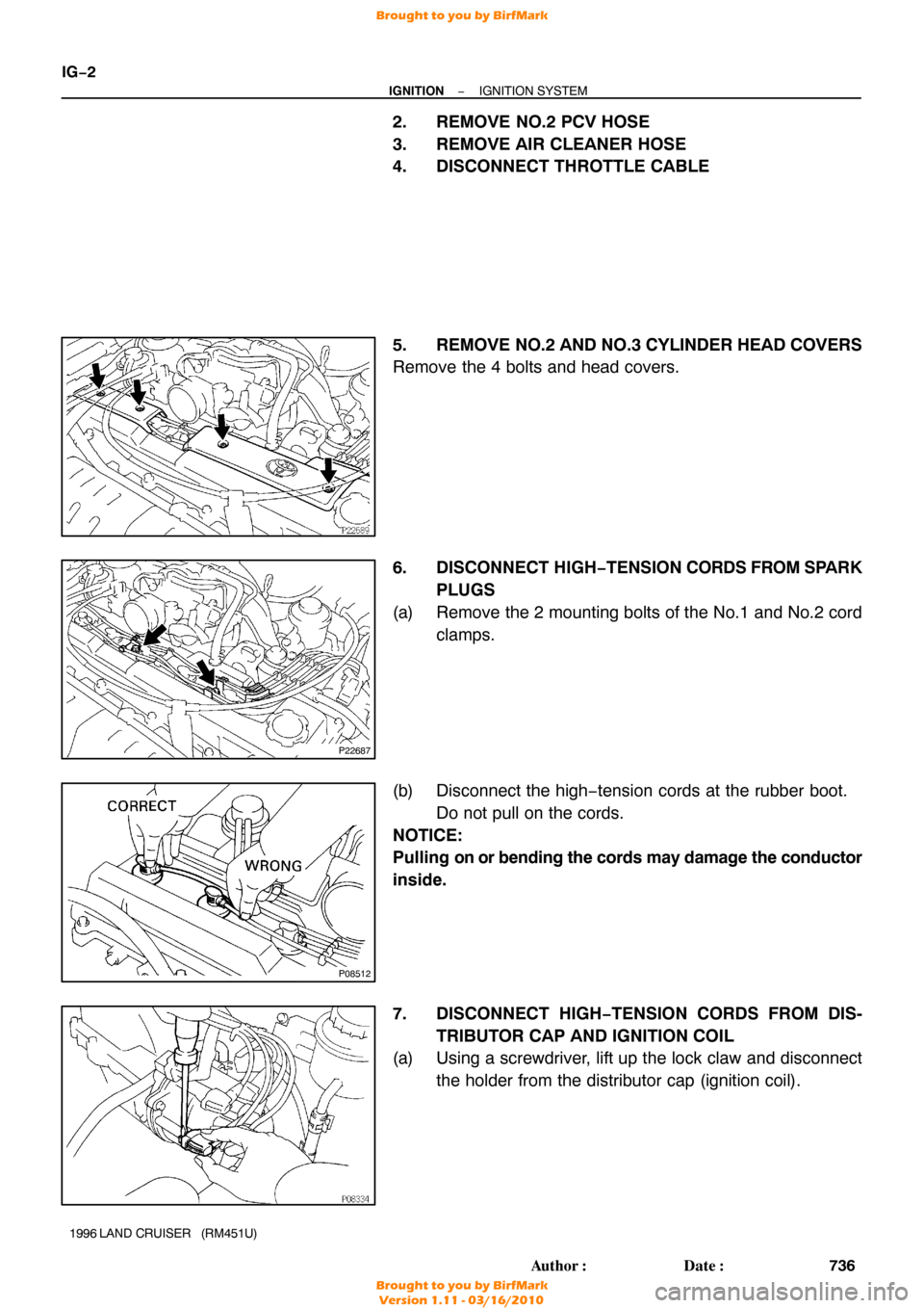
2. REMOVE NO.2 PCV HOSE
3. REMOVE AIR CLEANER HOSE
4. DISCONNECT THROTTLE CABLE
5. REMOVE NO.2 AND NO.3 CYLINDER HEAD COVERS
Remove the 4 bolts and head covers.
6. DISCONNECT HIGH −TENSION CORDS FROM SPARK
PLUGS
(a) Remove the 2 mounting bolts of the No.1 and No.2 cord clamps.
(b) Disconnect the high −tension cords at the rubber boot.
Do not pull on the cords.
NOTICE:
Pulling on or bending the cords may damage the conductor
inside.
7. DISCONNECT HIGH−TENSION CORDS FROM DIS- TRIBUTOR CAP AND IGNITION COIL
(a) Using a screwdriver, lift up the lock claw and disconnect
the holder from the distributor cap (ignition coil).
Brought to you by BirfMark
Brought to you by BirfMark
Version 1.11 - 03/16/2010

DISASSEMBLY
1. REMOVE DRIVE PLATE
Uniformly loosen and remove the drive plate bolts, in several
passes, in the sequ")

23. DISCONNECT CONNECTING ROD FROM PISTON
(a) Using a small screwdriver, pry out the 2 snap rings.
(b) Gradually heat t")

3. INSPECT BEARING OF OIL PUMP DRIVE SHAFT
GEAR
Check the bearing for pitting and scratches.
If the bearing is damaged, repla")