Page 835 of 1399
EM−50
−
ENGINE MECHANICAL CYLINDER HEAD
1996 LAND CRUISER (RM451U)
2. REPLACE SPARK PLUG TUBE GASKETS
(a) Using a screwdriver, pry out the tube gasket.
(b) Using SST and a hammer, tap in a new tube gasket as
shown in the illustration.
SST 09950 −60010 (09951 −00480), 09950 −70010
(09951 −07150)
(c) Apply a light coat of MP grease to the gasket lip.
Brought to you by BirfMark
Brought to you by BirfMark
Version 1.11 - 03/16/2010
Page 840 of 1399

−
ENGINE MECHANICAL CYLINDER HEAD
EM−55
1996 LAND CRUISER (RM451U)
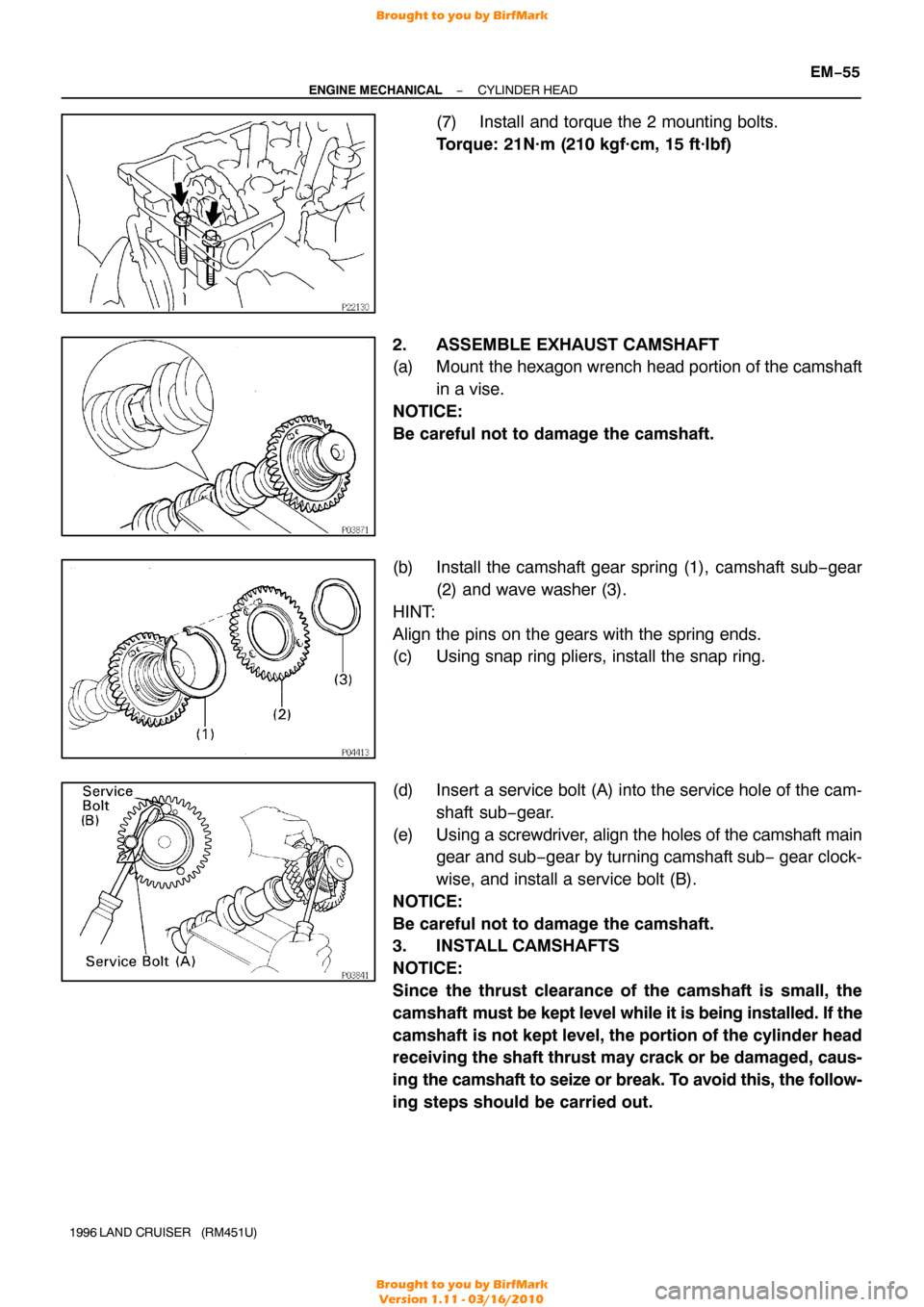
(7) Install and torque the 2 mounting bolts.
Torque: 21N·m (210 kgf·cm, 15 ft·lbf)
2. ASSEMBLE EXHAUST CAMSHAFT
(a) Mount the hexagon wrench head portion of the camshaft in a vise.
NOTICE:
Be careful not to damage the camshaft.
(b) Install the camshaft gear spring (1), camshaft sub −gear
(2) and wave washer (3).
HINT:
Align the pins on the gears with the spring ends.
(c) Using snap ring pliers, install the snap ring.
(d) Insert a service bolt (A) into the service hole of the cam- shaft sub−gear.
(e) Using a screwdriver, align the holes of the camshaft main
gear and sub− gear by turning camshaft sub − gear clock-
wise, and install a service bolt (B).
NOTICE:
Be careful not to damage the camshaft.
3. INSTALL CAMSHAFTS
NOTICE:
Since the thrust clearance of the camshaft is small, the
camshaft must be kept level while it is being installed. If the
camshaft is not kept level, the portion of the cylinder head
receiving the shaft thrust may crack or be damaged, caus-
ing the camshaft to seize or break. To avoid this, the follow-
ing steps should be carried out.
Brought to you by BirfMark
Brought to you by BirfMark
Version 1.11 - 03/16/2010
Page 841 of 1399

P22567A16077
2 Dot Marks
EM−56
−
ENGINE MECHANICAL CYLINDER HEAD
1996 LAND CRUISER (RM451U)
(a) Install the intake camshaft.
(1) Apply engine oil to the thrust portion of the intakecamshaft.
(2) Lightly place the intake camshaft on top of the cylin-
der head as shown in the illustration so that the No.
1 and No. 4 cylinder cam lobes face downward.
(3) Lightly push the camshaft towards the front without
applying excessive force.
(4) Place the No. 2 and No. 5 bearing caps in their prop-
er location.
(5) Temporarily tighten these bearing cap bolts uni- formly and alternately in several passes until the
bearing caps are snug with the cylinder head.
(6) Place the No. 3, No. 4, No. 6 and No. 7 bearing caps
in their proper location.
(7) Temporarily tighten these bearing cap bolts, alter- nately tightening the left and right bolts uniformly.
(8) Place the No. 1 bearing cap in its proper location. When doing this, check that there is no gap be-
tween the cylinder head and the contact surface of
bearing cap.
(9) Temporarily tighten the bearing cap bolts, alternate-
ly tightening the left and right bolts uniformly.
(10) Uniformly tighten the 14 bearing cap bolts in several
passes.
Torque: 16 N·m (160 kgf·cm, 12 ft·lbf)
(b) Install the exhaust camshaft. (1) Set the timing mark (2 dot marks) of the camshaftdrive gear at approx. 35 ° angle by turning the hexa-
gon wrench head portion of the intake camshaft
with a wrench.
Brought to you by BirfMark
Brought to you by BirfMark
Version 1.11 - 03/16/2010
Page 842 of 1399

−
ENGINE MECHANICAL CYLINDER HEAD
EM−57
1996 LAND CRUISER (RM451U)
(2) Apply engine oil to thrust portion of the exhaust
camshaft.
(3) Engage the exhaust camshaft gear to the intake
camshaft gear by matching the timing marks (two
dot marks) on each gear.
(4) Roll down the exhaust camshaft onto the bearing journals while engaging gears with each other.
(5) Lightly push the intake camshaft towards the front without applying excessive force.
(6) Install the No. 4 and No. 6 bearing caps in their proper location.
(7) Temporarily tighten the bearing cap bolts uniformly and alternately in several passes until the bearing
caps are snug with the cylinder head.
(8) Place the No. 2, No. 3, No. 5 and No. 7 bearing caps
in their proper location.
(9) Temporarily tighten these bearing cap bolts, alter- nately tightening the left and right bolts uniformly.
(10) Place the No. 1 bearing cap in its proper location. When doing this, check that there is no gap be-
tween the cylinder head and the contact surface of
bearing cap.
(11) Temporarily tighten the bearing cap bolts, alternate-
ly tightening the left and right bolts uniformly.
(12) Uniformly tighten the 14 bearing cap bolts in several
passes.
Torque: 16 N·m (160 kgf·cm, 12 ft·lbf)
(13) Bring the service bolt installed in the driven sub −
gear upward by turning the hexagon wrench head
portion of the camshaft with a wrench.
(14) Remove the service bolt.
(15) Check that the intake and exhaust camshafts turn smoothly.
Brought to you by BirfMark
Brought to you by BirfMark
Version 1.11 - 03/16/2010
Page 844 of 1399

Front Mark
P09890
Push
P08374A16075
1 Dot Mark
−
ENGINE MECHANICAL CYLINDER HEAD
EM−59
1996 LAND CRUISER (RM451U)
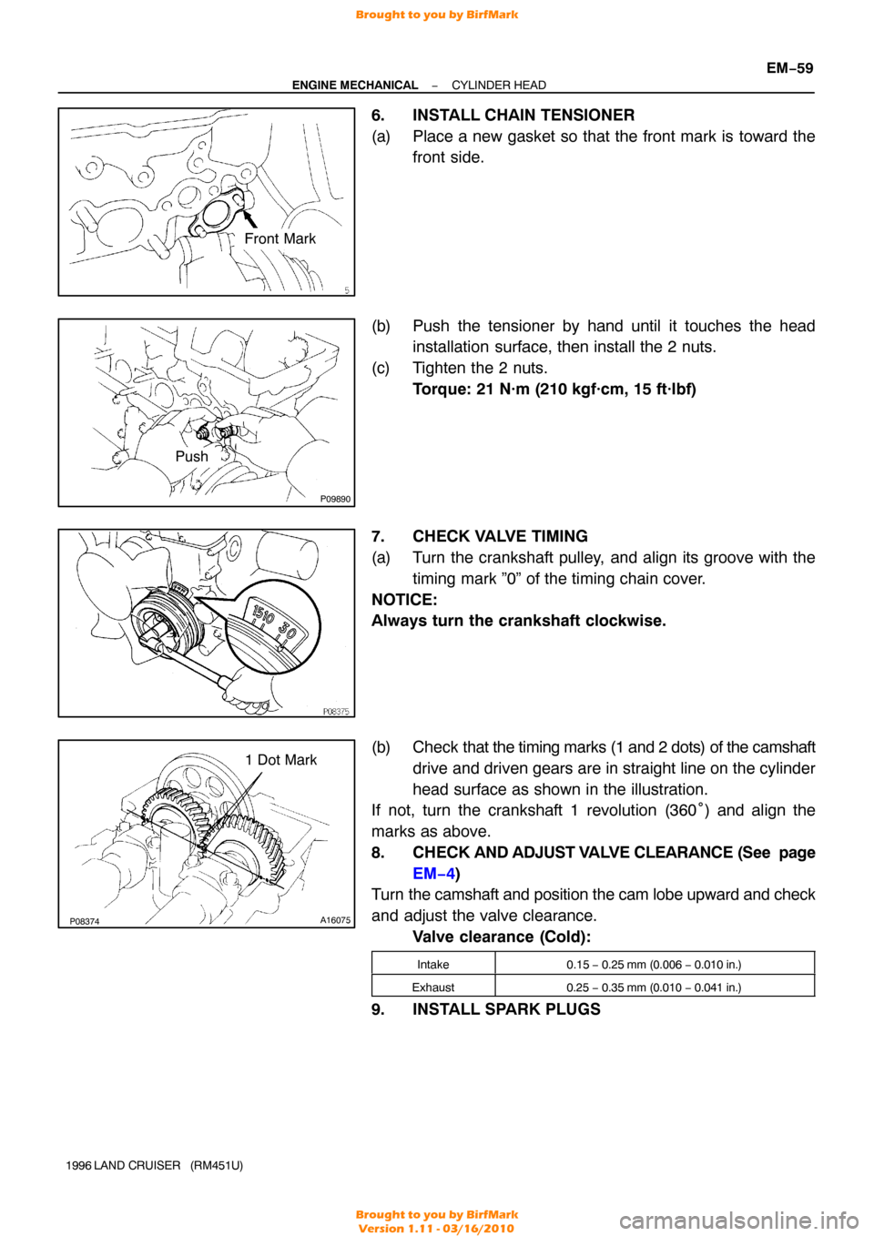
6. INSTALL CHAIN TENSIONER
(a) Place a new gasket so that the front mark is toward the
front side.
(b) Push the tensioner by hand until it touches the head installation surface, then install the 2 nuts.
(c) Tighten the 2 nuts. Torque: 21 N·m (210 kgf·cm, 15 ft·lbf)
7. CHECK VALVE TIMING
(a) Turn the crankshaft pulley, and align its groove with the timing mark ”0” of the timing chain cover.
NOTICE:
Always turn the crankshaft clockwise.
(b) Check that the timing marks (1 and 2 dots) of the camshaft
drive and driven gears are in straight line on the cylinder
head surface as shown in the illustration.
If not, turn the crankshaft 1 revolution (360° ) and align the
marks as above.
8. CHECK AND ADJUST VALVE CLEARANCE (See page
EM−4)
Turn the camshaft and position the cam lobe upward and check
and adjust the valve clearance.
Valve clearance (Cold):
Intake0.15 − 0.25 mm (0.006 − 0.010 in.)
Exhaust0.25 − 0.35 mm (0.010 − 0.041 in.)
9. INSTALL SPARK PLUGS
Brought to you by BirfMark
Brought to you by BirfMark
Version 1.11 - 03/16/2010
Page 847 of 1399

EM−62
−
ENGINE MECHANICAL CYLINDER HEAD
1996 LAND CRUISER (RM451U)
(h) Connect the engine wire to the intake manifold and cylin-
der block with the 2 bolts.
(i) Connect the PNP switch connector.
(j) Connect the 2 heated oxygen sensor connectors.
(k) Connect the connectors.
(1) Connect the Knock sensor connector.
(2) Connect the oil level sensor connector.
(3) Connect the 2 connectors to tthe ransmission.
(4) Connect the starter connector.
(l) Connect the engine wire to the cylinder block with the bolt.
(m) Connect the connectors.
(1) Connect the ECT sender gauge connector.
(2) Connect the ECT cut switch connector.
(3) Connect the ECT sensor connector.
(4) Connect the knock sensor connector.
(5) Connect the crankshaft position sensor connector.
19. CONNECT FUEL INLET HOSE
Connect the fuel inlet hose to the fuel filter with 2 new gaskets
and the union bolt. Torque: 29 N·m (300 kgf·cm, 22 ft·lbf)
20. INSTALL INTAKE MANIFOLD STAY
Install the intake manifold stay with the 2 bolts. Torque: 36 N·m (360 kgf·cm, 26 ft·lbf)
21. INSTALL OIL DIPSTICKS AND GUIDES FOR ENGINE AND TRANSMISSION
(a) Install a new O−ring to the dipstick guide.
(b) Apply a light coat of engine oil on the O −ring.
(c) Push in the dipstick guide into the guide hole of the oil pan.
(d) Install the dipstick guide with the 2 bolts. Torque: 20 N·m (200 kgf·cm, 14 ft·lbf)
22. INSTALL THROTTLE BODY (See page SF−48)
23. INSTALL GENERATOR AND DRIVE BELTS (See page CH−19 )
Brought to you by BirfMark
Brought to you by BirfMark
Version 1.11 - 03/16/2010
Page 855 of 1399

EM−70
−
ENGINE MECHANICAL ENGINE UNIT
1996 LAND CRUISER (RM451U)
13. DISCONNECT ENGINE WIRE AND HEATER VALVE
FROM COWL PANEL
(a) Remove the 2 bolts and disconnect the engine wire and
ground strap.
(b) Remove the 2 bolts and disconnect the heater valve.
14. DISCONNECT BRAKE BOOSTER VACUUM HOSE
15. DISCONNECT EVAP HOSE
16. DISCONNECT FUEL HOSES
(a) Disconnect the fuel return hose.
(b) Remove the union bolt and 2 gaskets, and disconnect the
fuel inlet hose from the fuel filter.
17. DISCONNECT WIRES AND CONNECTORS
(a) Disconnect the 2 heated oxygen sensor connectors.
(b) Disconnect the DLC1 clamp.
(c) Disconnect the 2 oil pressure gauge connectors.
(d) Disconnect the generator wire and connector.
(e) Disconnect the connector on the intake manifold from the
fender apron.
(f) Disconnect the high−tension cord from the ignition coil.
(g) Disconnect the ground strap from the No. 1 engine hang-
er.
(h) Disconnect the ground strap from the air intake chamber.
(i) Disconnect the starter wire.
(j) Disconnect the ground cable from the cylinder block.
18. DISCONNECT A/C COMPRESSOR AND BRACKET
(a) Loosen the idler pulley nut and adjusting bolt, and remove
the drive belt.
(b) Remove the 4 mounting bolts, and disconnect the com-
pressor from the bracket.
HINT:
Put aside the compressor, and suspend it.
(c) Remove the 5 bolts and A/C compressor bracket.
19. REMOVE RADIATOR PIPE
(a) Remove the 2 nuts holding the radiator pipe to the No. 1 oil pan.
(b) Disconnect the No. 2 radiator hose from the water inlet and remove the radiator pipe.
Brought to you by BirfMark
Brought to you by BirfMark
Version 1.11 - 03/16/2010
Page 865 of 1399

EM−80
−
ENGINE MECHANICAL ENGINE UNIT
1996 LAND CRUISER (RM451U)
19. CONNECT ENGINE WIRE TO CABIN
(a) Push in the engine wire through the cowl panel.
(b) Connect the connectors.
(1) Connect the 3 connectors to the ECM.
(2) Connect the 2 connectors to the cowl wire.
(c) Connect the A/C amplifier with the screw.
(d) Install the speaker panel with the screw.
(e) Install the glove compartment door with the 2 screws.
20. CONNECT PS RETURN HOSE
Connect the return hose to the PS reservoir tank.
21. CONNECT PS PRESSURE HOSE
Connect the PS pressure hose with 2 new gaskets and the
union bolt. Torque: 56 N·m (575 kgf·cm, 42 ft·lbf)
22. INSTALL RADIATOR PIPE
(a) Connect the No. 2 radiator hose to the water inlet.
(b) Install the 2 nuts holding the radiator pipe to the No. 1 oil pan.
Torque: 21 N·m (210 kgf·cm, 15 ft·lbf)
23. INSTALL A/C COMPRESSOR AND BRACKET
(a) Install the A/C compressor bracket with the 5 bolts.
Torque: 37 N·m (375 kgf·cm, 27 ft·lbf)
(b) Install the A/C compressor with the 4 bolts. Torque: 25 N·m (250 kgf·cm, 18 ft·lbf)
(c) Install and adjust the drive belt (See page CH−2).
24. CONNECT WIRES AND CONNECTORS
(a) Connect the 2 heated oxygen sensor connectors.
(b) Connect the DLC1 clamp.
(c) Connect the 2 oil pressure gauge connectors.
(d) Connect the generator wire and connector.
(e) Connect the connector on the intake manifold to the fend-
er apron.
(f) Connect the high −tension cord to the ignition coil.
(g) Connect the ground strap to the No. 1 engine hanger.
(h) Connect the ground strap to the air intake chamber.
(i) Connect the starter wire.
(j) Connect the ground cable to the cylinder block.
25. CONNECT FUEL HOSES
(a) Connect the fuel inlet hose to the fuel filter with 2 new gas-
kets and the union bolt.
Torque: 29 N·m (300 kgf·cm, 22 ft·lbf)
(b) Connect the fuel return hose.
Brought to you by BirfMark
Brought to you by BirfMark
Version 1.11 - 03/16/2010