Page 1171 of 1399
SA2621
SA−108
−
SUSPENSION AND AXLE DIFFERENTIAL LOCKING SYSTEM
1996 LAND CRUISER (RM451U)
(f) Remove the shift fork set bolt.
(g) Remove the 4 bolts.
(h) Using a screwdriver, pry out the actuator.
Brought to you by BirfMark
Brought to you by BirfMark
Version 1.11 - 03/16/2010
Page 1172 of 1399
SA1VO−02
Z07259
Outside
Actuator Installation
Hole Shift Fork
R08154
3
2
1.5
50 °
108 °
Matchmark
(Groove)
SA2306
SA2420
−
SUSPENSION AND AXLE DIFFERENTIAL LOCKING SYSTEM
SA−109
1996 LAND CRUISER (RM451U)
INSTALLATION
1. INSTALL FRONT ACTUATOR
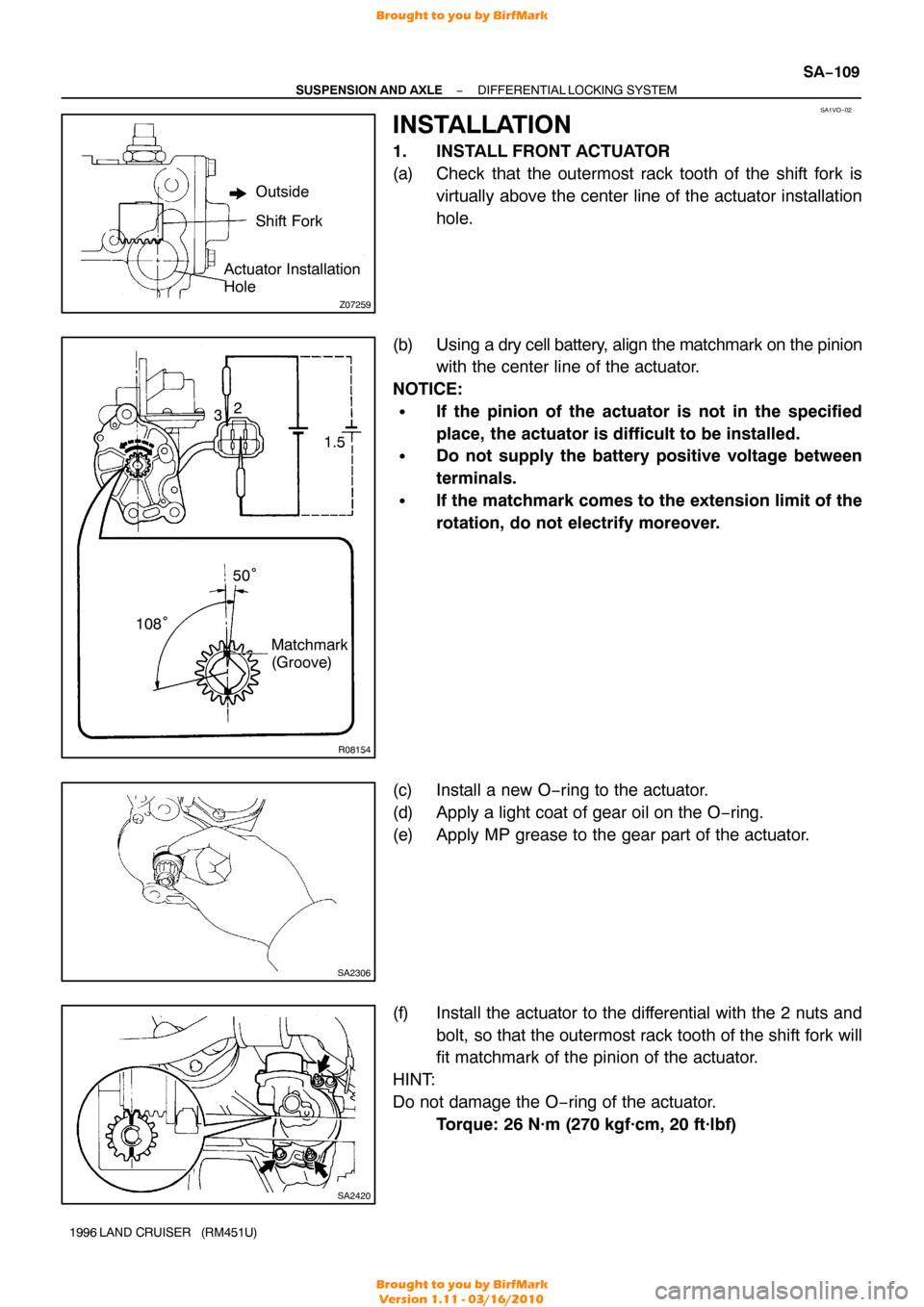
(a) Check that the outermost rack tooth of the shift fork is
virtually above the center line of the actuator installation
hole.
(b) Using a dry cell battery, alig n the matchmark on the pinion
with the center line of the actuator.
NOTICE:
�If the pinion of the actuator is not in the specified
place, the actuator is difficult to be installed.
�Do not supply the battery positive voltage between
terminals.
�If the matchmark comes to the extension limit of the
rotation, do not electrify moreover.
(c) Install a new O−ring to the actuator.
(d) Apply a light coat of gear oil on the O −ring.
(e) Apply MP grease to the gear part of the actuator.
(f) Install the actuator to the differential with the 2 nuts and bolt, so that the outermost rack tooth of the shift fork will
fit matchmark of the pinion of the actuator.
HINT:
Do not damage the O −ring of the actuator.
Torque: 26 N·m (270 kgf·cm, 20 ft·lbf)
Brought to you by BirfMark
Brought to you by BirfMark
Version 1.11 - 03/16/2010
Page 1173 of 1399
Z15220
FIPG Width Approx.
1 − 2 mm (0.04 − 0.08 in.)
Z07262Adhesive
SA2620
SA−11 0
−
SUSPENSION AND AXLE DIFFERENTIAL LOCKING SYSTEM
1996 LAND CRUISER (RM451U)
(g) Connect the connector and tube.
HINT:
�The depth of the insertion of the bleeder tube into the
hose is approx. 15 mm (0.59 in.).
�Take care that water or the equivalent will not adhere to
the connector and hose.
(h) Cancel the front differential lock.
With the ignition switch ON, turn the differential lock con-
trol switch to OFF to cancel the differential lock.
2. INSTALL REAR ACTUATOR
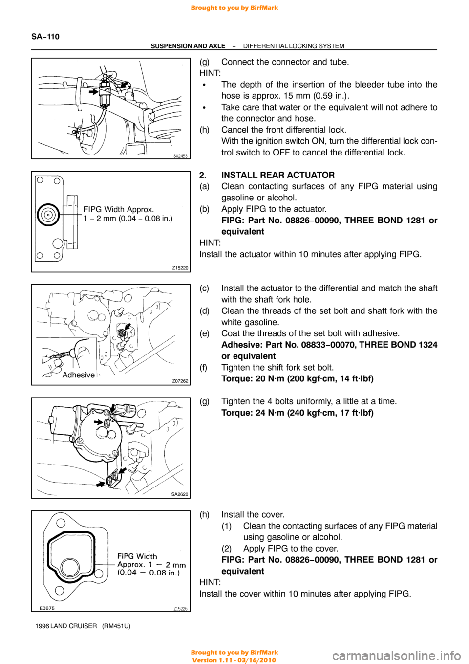
(a) Clean contacting surfaces of any FIPG material using gasoline or alcohol.
(b) Apply FIPG to the actuator. FIPG: Part No. 08826−00090, THREE BOND 1281 or
equivalent
HINT:
Install the actuator within 10 minutes after applying FIPG.
(c) Install the actuator to the differential and match the shaft with the shaft fork hole.
(d) Clean the threads of the set bolt and shaft fork with the white gasoline.
(e) Coat the threads of the set bolt with adhesive.
Adhesive: Part No. 08833 −00070, THREE BOND 1324
or equivalent
(f) Tighten the shift fork set bolt. Torque: 20 N·m (200 kgf·cm, 14 ft·lbf)
(g) Tighten the 4 bolts uniformly, a little at a time. Torque: 24 N·m (240 kgf·cm, 17 ft·lbf)
(h) Install the cover. (1) Clean the contacting surfaces of any FIPG material
using gasoline or alcohol.
(2) Apply FIPG to the cover.
FIPG: Part No. 08826−00090, THREE BOND 1281 or
equivalent
HINT:
Install the cover within 10 minutes after applying FIPG.
Brought to you by BirfMark
Brought to you by BirfMark
Version 1.11 - 03/16/2010
Page 1174 of 1399
SA2619
Z07261
−
SUSPENSION AND AXLE DIFFERENTIAL LOCKING SYSTEM
SA−111
1996 LAND CRUISER (RM451U)
(3) Tighten the 3 bolts.
Torque: 18 N·m (185 kgf·cm, 13 ft·lbf)
(i) Install the rear Diff. position switch. Install the position switch with a new gasket.
Torque: 40 N·m (410 kgf·cm, 30 ft·lbf)
(j) Connect the connectors and tube.
HINT:
�The depth of the insertion of the bleeder tube into the
hose is approx. 15 mm (0.59 in.).
�Take care that the water or the equivalent will not adhere
to the connectors and hose.
(k) Install the actuator protector. Install the protector with the 2 nuts and bolt.
Torque:
Nut: 35 N·m (360 kgf·cm, 26 ft·lbf)
Bolt: 20 N·m (200 kgf·cm, 14 ft·lbf)
(l) Cancel the rear differential lock. With the ignition switch ON, turn the differential lock con-
trol switch to OFF to cancel the differential lock.
Brought to you by BirfMark
Brought to you by BirfMark
Version 1.11 - 03/16/2010
Page 1216 of 1399
FI4848
FI4849
SF−30
−
SFI INJECTOR
1996 LAND CRUISER (RM451U)
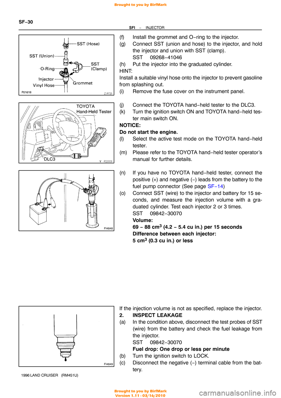
(f) Install the grommet and O−ring to the injector.
(g) Connect SST (union and hose) to the injector, and hold
the injector and union with SST (clamp).
SST 09268−41046
(h) Put the injector into the graduated cylinder.
HINT:
Install a suitable vinyl hose onto the injector to prevent gasoline
from splashing out.
(i) Remove the fuse cover on the instrument panel.
(j) Connect the TOYOTA hand−held tester to the DLC3.
(k) Turn the ignition switch ON and TOYOTA hand−held tes-
ter main switch ON.
NOTICE:
Do not start the engine.
(l) Select the active test mode on the TOYOTA hand −held
tester.
(m) Please refer to the TOYOTA hand −held tester operator’s
manual for further details.
(n) If you have no TOYOTA hand−held tester, connect the positive (+) and negative (−) leads from the battery to the
fuel pump connector (See page SF−14)
(o) Connect SST (wire) to the injector and battery for 15 se- conds, and measure the injection volume with a gra-
duated cylinder. Test each injector 2 or 3 times.
SST 09842−30070
Volume:
69 − 88 cm
3 (4.2 − 5.4 cu in.) per 15 seconds
Difference between each injector:
5 cm
3 (0.3 cu in.) or less
If the injection volume is not as specified, replace the injector.
2. INSPECT LEAKAGE
(a) In the condition above, disconnect the test probes of SST (wire) from the battery and check the fuel leakage from
the injector.
SST 09842−30070
Fuel drop: One drop or less per minute
(b) Turn the ignition switch to LOCK.
(c) Disconnect the negative ( −) terminal cable from the bat-
tery.
Brought to you by BirfMark
Brought to you by BirfMark
Version 1.11 - 03/16/2010
Page 1259 of 1399
Z15499
PS GearSSTPS Vane
Pump
Oil
Reservoir
Open
Z15500
PS Gear
SSTPS Vane
Pump
Oil
Reservoir
Open
Lock Position
SR−6
−
STEERING POWER STEERING FLUID
1996 LAND CRUISER (RM451U)
(g) With the engine idling, open the valve fully.
(h) Measure the fluid pressure at engine speeds of 1,000 rpm
and 3,000 rpm.
Difference fluid pressure:
490 kPa (5 kgf/cm
2, 71 psi) or less
NOTICE:
Do not turn the steering wheel.
(i) With the engine idling and valve fully opened, turn the steering wheel to full lock.
Minimum fluid pressure:
9,316 kPa (95 kgf/cm
2, 1,351 psi)
NOTICE:
�Do not maintain lock position for more than 10 se-
conds.
�Do not let the fluid temperature become too high.
(j) Disconnect the SST.
(k) Connect the pressure feed tube (See page SR−32).
(l) Bleed the power steering system (See page SR−3).
Brought to you by BirfMark
Brought to you by BirfMark
Version 1.11 - 03/16/2010
Page 1305 of 1399
SS1EO−04
SS−4
−
SERVICE SPECIFICATIONS ENGINE MECHANICAL
127
Author�: Date�:
1996 LAND CRUISER (RM451U)
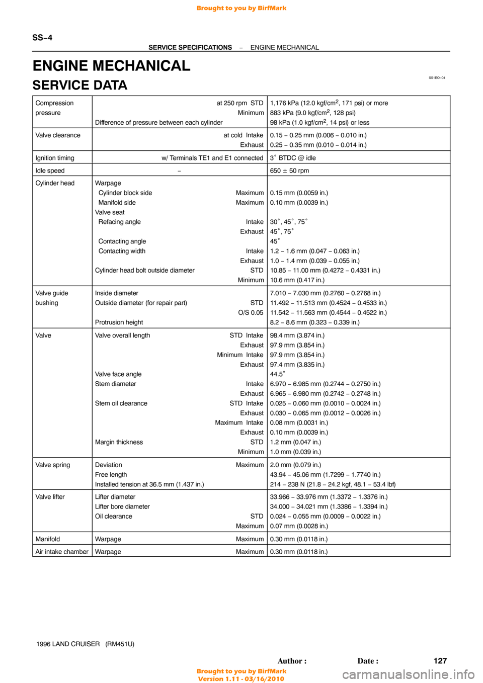
ENGINE MECHANICAL
SERVICE DATA
Compression
pressureat 250 rpm STD
Minimum
Difference of pressure between each cylinder1,176 kPa (12.0 kgf/cm2, 171 psi) or more
883 kPa (9.0 kgf/cm2, 128 psi)
98 kPa (1.0 kgf/cm2, 14 psi) or less
Valve clearanceat cold Intake Exhaust0.15 − 0.25 mm (0.006 − 0.010 in.)
0.25 − 0.35 mm (0.010 − 0.014 in.)
Ignition timingw/ Terminals TE1 and E1 connected3° BTDC @ idle
Idle speed−650 ± 50 rpm
Cylinder headWarpage
Cylinder block side Maximum
Manifold side Maximum
Valve seat
Refacing angle Intake
Exhaust
Contacting angle
Contacting width Intake
Exhaust
Cylinder head bolt outside diameter STD
Minimum
0.15 mm (0.0059 in.)
0.10 mm (0.0039 in.)
30°, 45° , 75°
45 °, 75°
45 °
1.2 − 1.6 mm (0.047 − 0.063 in.)
1.0 − 1.4 mm (0.039 − 0.055 in.)
10.85 − 11.00 mm (0.4272 − 0.4331 in.)
10.6 mm (0.417 in.)
Valve guide
bushingInside diameter
Outside diameter (for repair part) STD O/S 0.05
Protrusion height7.010 − 7.030 mm (0.2760 − 0.2768 in.)
11.492 − 11.513 mm (0.4524 − 0.4533 in.)
11.542 − 11.563 mm (0.4544 − 0.4522 in.)
8.2 − 8.6 mm (0.323 − 0.339 in.)
ValveValve overall length STD Intake
Exhaust
Minimum Intake Exhaust
Valve face angle
Stem diameter Intake
Exhaust
Stem oil clearance STD Intake
Exhaust
Maximum Intake
Exhaust
Margin thickness STD
Minimum98.4 mm (3.874 in.)
97.9 mm (3.854 in.)
97.9 mm (3.854 in.)
97.4 mm (3.835 in.)
44.5 °
6.970 − 6.985 mm (0.2744 − 0.2750 in.)
6.965 − 6.980 mm (0.2742 − 0.2748 in.)
0.025 − 0.060 mm (0.0010 − 0.0024 in.)
0.030 − 0.065 mm (0.0012 − 0.0026 in.)
0.08 mm (0.0031 in.)
0.10 mm (0.0039 in.)
1.2 mm (0.047 in.)
1.0 mm (0.039 in.)
Valve springDeviation Maximum
Free length
Installed tension at 36.5 mm (1.437 in.)2.0 mm (0.079 in.)
43.94 − 45.06 mm (1.7299 − 1.7740 in.)
214 − 238 N (21.8 − 24.2 kgf, 48.1 − 53.4 lbf)
Valve lifterLifter diameter
Lifter bore diameter
Oil clearance STD
Maximum33.966 − 33.976 mm (1.3372 − 1.3376 in.)
34.000 − 34.021 mm (1.3386 − 1.3394 in.)
0.024 − 0.055 mm (0.0009 − 0.0022 in.)
0.07 mm (0.0028 in.)
ManifoldWarpage Maximum0.30 mm (0.0118 in.)
Air intake chamberWarpageMaximum0.30 mm (0.0118 in.)
Brought to you by BirfMark
Brought to you by BirfMark
Version 1.11 - 03/16/2010
Page 1309 of 1399
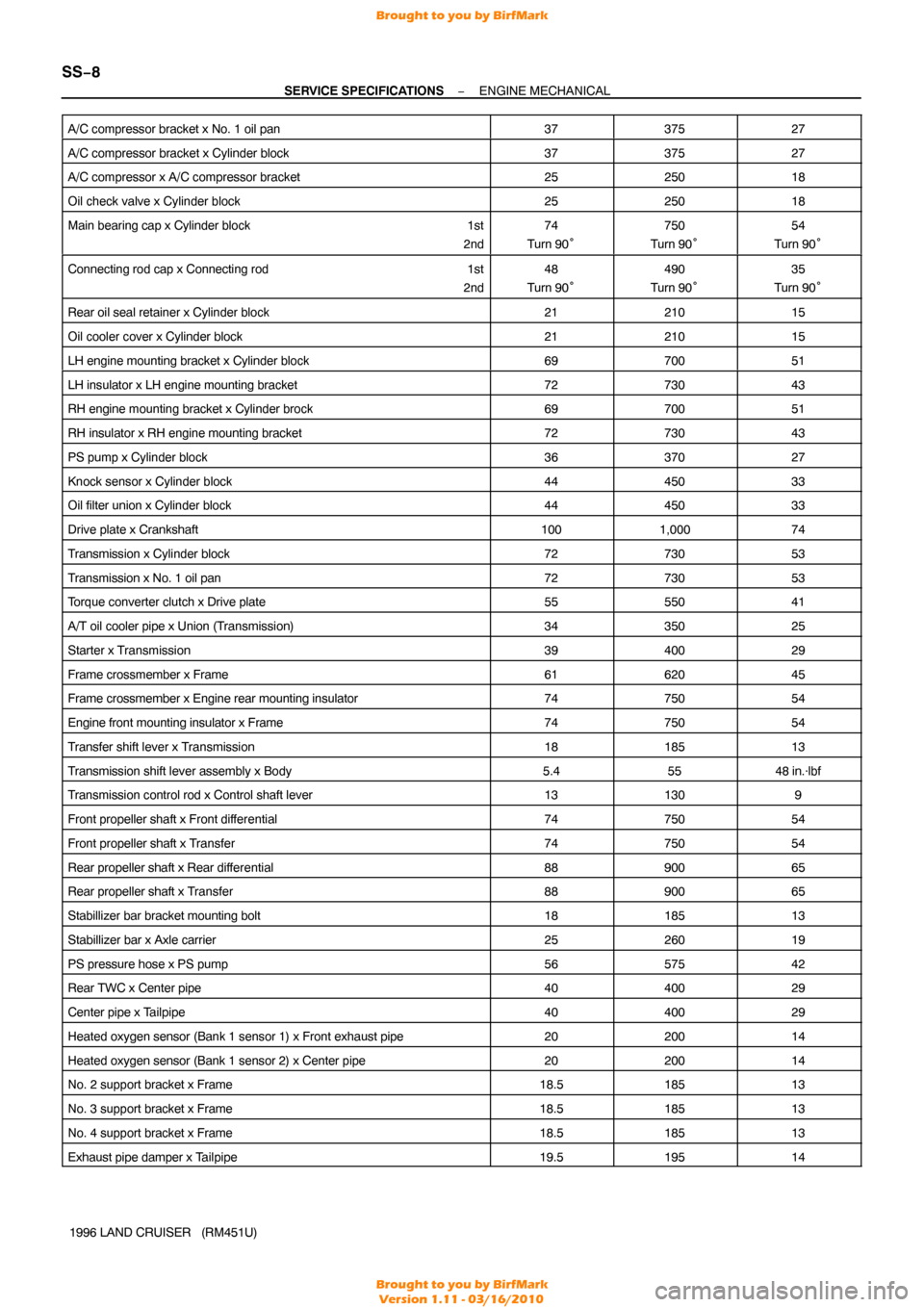
SS−8
−
SERVICE SPECIFICATIONS ENGINE MECHANICAL
1996 LAND CRUISER (RM451U)
A/C compressor bracket x No. 1 oil pan
3737527
A/C compressor bracket x Cylinder block3737527
A/C compressor x A/C compressor bracket2525018
Oil check valve x Cylinder block2525018
Main bearing cap x Cylinder block
1st
2nd74
Turn 90°750
Turn 90°54
Turn 90°
Connecting rod cap x Connecting rod 1st
2nd48
Turn 90°490
Turn 90°35
Turn 90°
Rear oil seal retainer x Cylinder block2121015
Oil cooler cover x Cylinder block2121015
LH engine mounting bracket x Cylinder block6970051
LH insulator x LH engine mounting bracket7273043
RH engine mounting bracket x Cylinder brock6970051
RH insulator x RH engine mounting bracket7273043
PS pump x Cylinder block3637027
Knock sensor x Cylinder block4445033
Oil filter union x Cylinder block4445033
Drive plate x Crankshaft1001,00074
Transmission x Cylinder block7273053
Transmission x No. 1 oil pan7273053
Torque converter clutch x Drive plate5555041
A/T oil cooler pipe x Union (Transmission)3435025
Starter x Transmission3940029
Frame crossmember x Frame6162045
Frame crossmember x Engine rear mounting insulator7475054
Engine front mounting insulator x Frame7475054
Transfer shift lever x Transmission1818513
Transmission shift lever assembly x Body5.45548 in.·lbf
Transmission control rod x Control shaft lever131309
Front propeller shaft x Front dif ferential7475054
Front propeller shaft x Transfer7475054
Rear propeller shaft x Rear differential8890065
Rear propeller shaft x Transfer8890065
Stabillizer bar bracket mounting bolt1818513
Stabillizer bar x Axle carrier2526019
PS pressure hose x PS pump5657542
Rear TWC x Center pipe4040029
Center pipe x Tailpipe4040029
Heated oxygen sensor (Bank 1 sensor 1) x Front exhaust pipe2020014
Heated oxygen sensor (Bank 1 sensor 2) x Center pipe2020014
No. 2 support bracket x Frame18.518513
No. 3 support bracket x Frame18.518513
No. 4 support bracket x Frame18.518513
Exhaust pipe damper x Tailpipe19.519514
Brought to you by BirfMark
Brought to you by BirfMark
Version 1.11 - 03/16/2010