Page 1139 of 1399
SA1VF−03
SA−76
−
SUSPENSION AND AXLE REAR DIFFERENTIAL CARRIER
933
Author�: Date�:
1996 LAND CRUISER (RM451U)
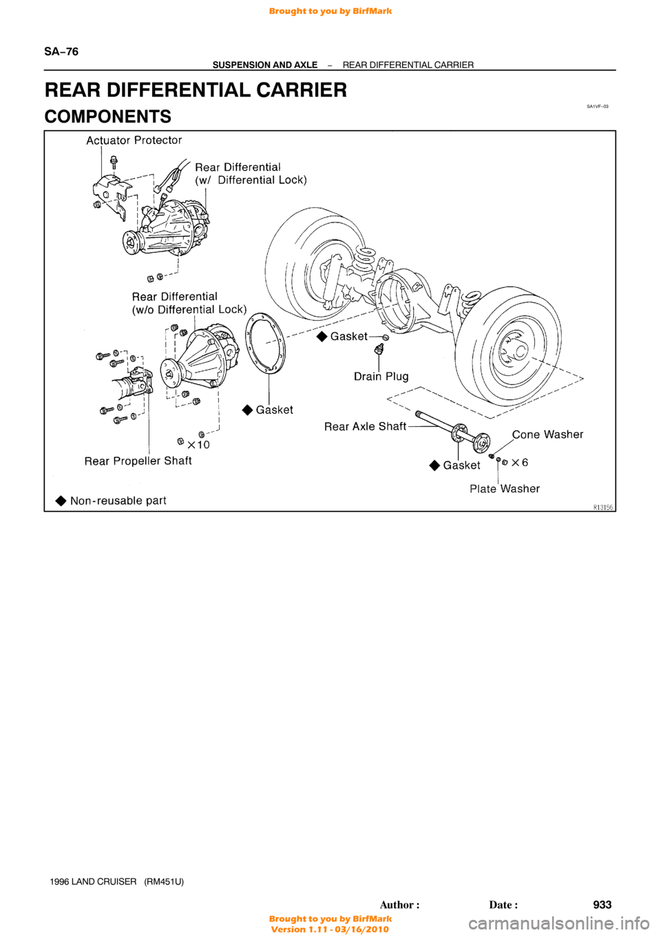
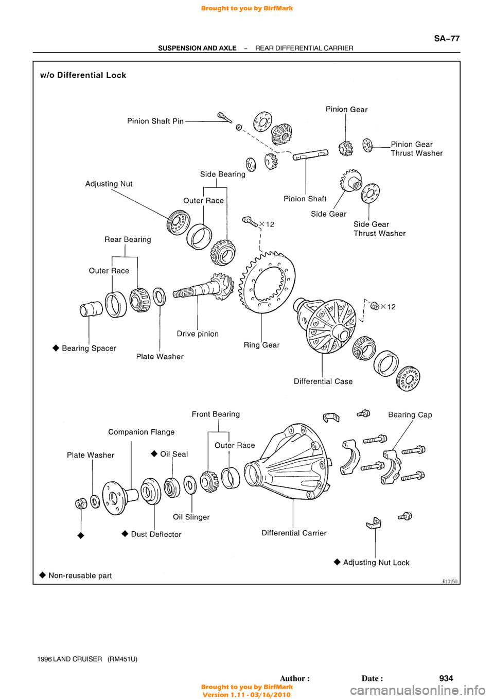
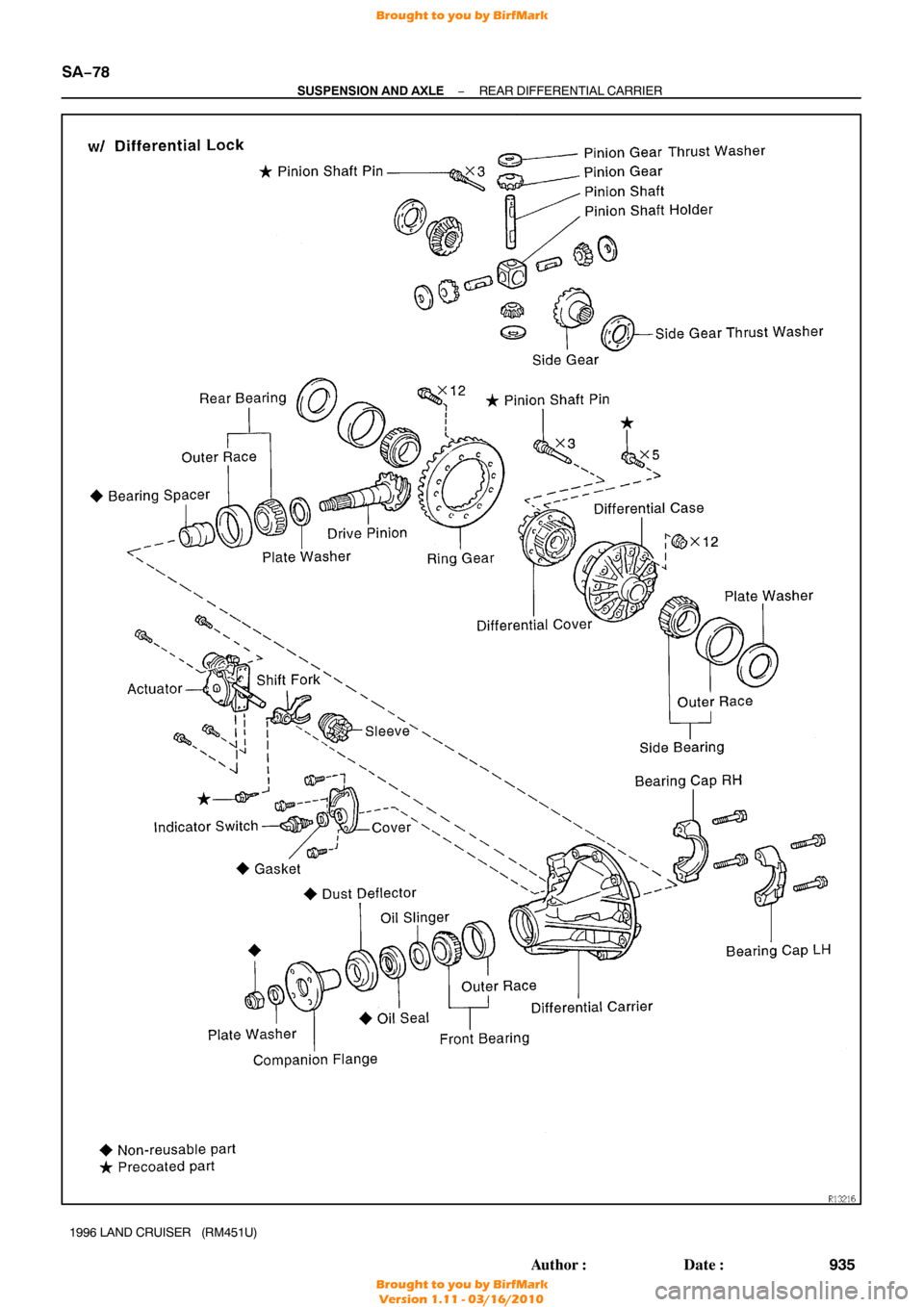
REAR DIFFERENTIAL CARRIER
COMPONENTS
Brought to you by BirfMark
Brought to you by BirfMark
Version 1.11 - 03/16/2010
Page 1140 of 1399
−
SUSPENSION AND AXLE REAR DIFFERENTIAL CARRIER
SA−77
934
Author�: Date�:
1996 LAND CRUISER (RM451U)
Brought to you by BirfMark
Brought to you by BirfMark
Version 1.11 - 03/16/2010
Page 1141 of 1399
SA−78
−
SUSPENSION AND AXLE REAR DIFFERENTIAL CARRIER
935
Author�: Date�:
1996 LAND CRUISER (RM451U)
Brought to you by BirfMark
Brought to you by BirfMark
Version 1.11 - 03/16/2010
Page 1142 of 1399
SA24T−01
SA2310
−
SUSPENSION AND AXLE REAR DIFFERENTIAL CARRIER
SA−79
1996 LAND CRUISER (RM451U)
REMOVAL
1. w/ Differential lock:
SHIFT REAR DIFFERENTIAL TO LOCK
(a) Turn the ignition switch to the ON position.
(b) Keep the center differential lock condition.
(c) Turn the differential lock control switch to the RR or FR/ RR position and lock the rear differential.
HINT:
Rotating the tires, check they are in the differential lock condi-
tion.
(d) Disconnect the cable from the negative terminal of the battery.
2. DRAIN DIFFERENTIAL OIL
3. REMOVE REAR AXLE SHAFTS (See page SA−63 )
4. DISCONNECT PROPELLER SHAFT (See page PR−3 )
5. REMOVE DIFFERENTIAL CARRIER ASSEMBLY
(a) Remove the 10 nuts, washers and differential carrier as- sembly.
NOTICE:
Be careful not to damage the installation surface. Torque: 73 N·m (740 kgf·cm, 54 ft·lbf)
(b) Remove the gasket.
Brought to you by BirfMark
Brought to you by BirfMark
Version 1.11 - 03/16/2010
Page 1143 of 1399

SA1VH−04
SA2446
SA−80
−
SUSPENSION AND AXLE REAR DIFFERENTIAL CARRIER
1996 LAND CRUISER (RM451U)
DISASSEMBLY
1. CHECK RUNOUT OF COMPANION FLANGE
Using a dial indicator")
W00493
30 mm
(1.18 in.)
SA1VH−04
SA2446
SA−80
−
SUSPENSION AND AXLE REAR DIFFERENTIAL CARRIER
1996 LAND CRUISER (RM451U)
DISASSEMBLY
1. CHECK RUNOUT OF COMPANION FLANGE
Using a dial indicator, measure the vertical and lateral runout of
the companion flange. Maximum runout: 0.10 mm (0.0039 in.)
2. CHECK RING GEAR RUNOUT
Using a dial indicator, measure the ring gear runout. Maximum runout: 0.10 mm (0.0039 in.)
If the runout is greater than the maximum, replace the ring gear.
3. CHECK RING GEAR BACKLASH
Using a dial indicator, measure the ring gear backlash. Backlash: 0.15 − 0.20 mm (0.0059 − 0.0079 in.)
HINT:
Perform the measurements at 3 or more positions around the
circumference of the ring gear.
If the backlash is not within the specification, adjust the side
bearing preload or repair as necessary.
4. MEASURE DRIVE PINION PRELOAD
(a) Using a torque wrench, measure the preload of backlash between the drive pinion and ring gear.
Preload (at starting):
0.7 − 1.0 N·m (7 − 10 kgf·cm, 6.1 − 8.7 in.·lbf)
(b) Using a torque wrench, measure the preload. Total preload (at starting):
Drive pinion preload plus
w/o Differential lock
0.4 − 0.6 N·m (4 − 6 kgf·cm, 3.5 − 5.2 in.·lbf)
w/ differential lock
0.3 − 0.7 N·m (3 − 7 kgf·cm, 2.6 − 6.1 in.·lbf)
If necessary, disassemble and inspect the differential.
Brought to you by BirfMark
Brought to you by BirfMark
Version 1.11 - 03/16/2010
Page 1144 of 1399

5. CHECK SIDE GEAR BACKLASH
Using a dial indicator, measure the side gear backlash with")
SA2131
SA2134
SA2448
SST
−
SUSPENSION AND AXLE REAR DIFFERENTIAL CARRIER
SA−81
1996 LAND CRUISER (RM451U)
5. CHECK SIDE GEAR BACKLASH
Using a dial indicator, measure the side gear backlash with
holding one pinion gear toward the case.
Backlash: 0.02 − 0.20 mm (0.0008 − 0.0079 in.)
If the backlash is not within the specification, install the correct
thrust washers (See page SA−87).
6. CHECK TOOTH CONTACT BETWEEN RING GEAR
AND DRIVE PINION (See page SA−35 )
7. w/ DIFFERENTIAL LOCK: REMOVE INDICATOR SWITCH
Remove the indicator switch and gasket.
8. w/ DIFFERENTIAL LOCK: REMOVE COVER
(a) Remove the 3 bolts.
(b) Using a brass bar and hammer, tap on the cover to re- move it.
9. w/ DIFFERENTIAL LOCK: REMOVE SLEEVE
(a) Remove the 4 bolts.
(b) Using a plastic hammer, tap the actuator.
(c) Remove the actuator and sleeve.
10. w/ DIFFERENTIAL LOCK: REMOVE ACTUATOR AND SHIFT FORK AND SHAFT
(a) Remove the shift fork shaft bolt.
(b) Pull out the actuator and remove the shift fork.
11. REMOVE COMPANION FLANGE
(a) Using a chisel and hammer, unstick the nut.
(b) Using SST to hold the flange, remove the nut and plate washer.
SST 09330−00021
Brought to you by BirfMark
Brought to you by BirfMark
Version 1.11 - 03/16/2010
Page 1145 of 1399

(c) Using SST, remove the companion flange.
SST 09950 −30010 (09951 �")
R13166
SST
SA2348
SST
Z00641
SST
SSTSST
SA−82
−
SUSPENSION AND AXLE REAR DIFFERENTIAL CARRIER
1996 LAND CRUISER (RM451U)
(c) Using SST, remove the companion flange.
SST 09950 −30010 (09951 −03010, 09953 −03010,
09954 −03010, 09955 −03030, 09956−03020)
12. REMOVE OIL SEAL AND OIL SLINGER
(a) Using SST, remove the oil seal from the dif ferential carrier.
SST 09308−10010
(b) Remove the oil slinger.
13. REMOVE FRONT BEARING
Using SST, remove the front bearing from the drive pinion. SST 09556−22010
If the front bearing is damaged or worn, replace the bearing.
14. w/o DIFFERENTIAL LOCK: REMOVE DIFFERENTIAL CASE ASSEMBLY
(a) Place matchmarks on the bearing cap and dif ferential car-
rier.
(b) Remove the 2 adjusting nut locks.
HINT:
Tag the disassembled parts to show the location for reassemb-
ly.
(c) Remove the 2 bearing caps and adjusting nuts.
(d) Remove the differential case with the bearing outer races
from the carrier.
Brought to you by BirfMark
Brought to you by BirfMark
Version 1.11 - 03/16/2010
Page 1146 of 1399

15. w/ DIFFERENTIAL LOCK:
REMOVE DIFFERENTIAL CASE ASSEMBLY
(a) Pla")
SA2437Matchmarks
R08254
SST
Z06911
SST
SA2424
−
SUSPENSION AND AXLE REAR DIFFERENTIAL CARRIER
SA−83
1996 LAND CRUISER (RM451U)
15. w/ DIFFERENTIAL LOCK:
REMOVE DIFFERENTIAL CASE ASSEMBLY
(a) Place matchmarks on the bearing cap and dif ferential car-
rier.
(b) Remove the 4 bolts and 2 bearing caps.
(c) Using SST, remove the plate washers. SST 09504−22011
HINT:
Measure the plate washer thickness and note it.
(d) Remove the differential case with the side bearing outer races from the differential carrier.
HINT:
Tag the bearing outer races to show the location for reassembly.
16. REMOVE DRIVE PINION AND BEARING SPACER FROM DIFFERENTIAL CARRIER
(a) Remove the drive pinion with the rear bearing.
(b) Remove the bearing spacer.
17. REMOVE DRIVE PINION REAR BEARING
(a) Using SST and a press, remove the rear bearing from the
drive pinion.
SST 09950−00020
HINT:
If the drive pinion or ring gear are damaged, replace them as
a set.
(b) Remove the plate washer from the drive pinion.
18. REMOVE FRONT AND REAR BEARING OUTER
RACES
Using a brass bar and hammer, remove the outer races.
Brought to you by BirfMark
Brought to you by BirfMark
Version 1.11 - 03/16/2010

REMOVAL
1. w/ Differential lock:
SHIFT REAR DIFFERENTIAL TO LOCK
(a) Turn the ignition switch t")