Page 1655 of 2890
, 100 minutes (AT)
Cold cranking ampere 430 amperes (MT), 490 amperes (AT)
Fuse10 A, 15 A, 20 A
Combination
meterSpeedometer")
1. Body Electrical
A: SPECIFICATIONS
BatteryReserve capacity 82 minutes (MT), 100 minutes (AT)
Cold cranking ampere 430 amperes (MT), 490 amperes (AT)
Fuse10 A, 15 A, 20 A
Combination
meterSpeedometer Electric pulse type
Tachometer Electric impulse type
Water temperature gauge Thermistor cross coil type
Fuel gauge Resistance cross coil type
Charge indicator light 12 V—1.4 W
Brake fluid level warning/parking brake indicator light 12 V—1.4 W
AT oil temperature warning light (AWD only) 12 V—1.4 W
A.B.S. warning light 12 V—1.4 W
CHECK ENGINE warning light
(Malfunction indicator lamp)12 V—1.4 W
Oil pressure warning light 12 V—1.4 W
AIRBAG system warning light 12 V—1.4 W
Low fuel warning light 12 V—3W
FWD indicator light 12 V—1.4 W
TCS warning light 12 V—1.4 W
TCS indicator light 12 V—1.4 W
Turn signal indicator light 12 V—1.4 W (2 pieces)
Seat belt warning light 12 V—1.4 W
Door open warning light 12 V—1.4 W
Headlight beam indicator light 12 V—1.4 W
Meter illumination light12 V—3 W (2 pieces)
12 V—3.4 W (4 pieces)
Headlight 12 V—60/55 W (Halogen)
Front clearance light 12 V—5W
Turn signal lightFront 12 V—21 W
Rear 12 V—21 W
Tail/Stop light 12 V—5/21 W
Back-up light 12 V—21 W
High-mount stop light12 V—18 W (SEDAN), 12 V—13 W
(WAGON)
License plate light 12 V—5W
Room light 12 V—8W
Trunk room light (SEDAN) 12 V—5W
Luggage room light (WAGON) 12 V—5W
Spot light 12 V—8 W (2 pieces)
Glove box light 12 V—3.4 W
Ash tray illumination light 12 V—1.7 W
Selector lever illumination light (AT model) 12 V—1.7 W
2
6-2SPECIFICATIONS
1. Body Electrical
Page 1659 of 2890
 External parts
Check for the existence of dirt or cracks on the battery
case, top cover, vent plugs, and terminal posts. If
necessary, clean with water and wipe with a dry")
B: INSPECTION
1. BATTERY
1) External parts
Check for the existence of dirt or cracks on the battery
case, top cover, vent plugs, and terminal posts. If
necessary, clean with water and wipe with a dry cloth.
Apply a thin coat of grease on the terminal posts to prevent
corrosion.
2) Electrolyte level
Check the electrolyte level in each cell. If the level is below
MIN LEVEL, bring the level to MAX LEVEL by pouring dis-
tilled water into the battery cell. Do not fill beyond MAX
LEVEL.
WARNING:
�Electrolyte has toxicity; be careful handling the
fluid.
�Avoid contact with skin, eyes or clothing. Especially
at contact with eyes, blush with water for 15 minutes
and get prompt medical attention.
�Batteries produce explosive gasses. Keep sparks,
flame, cigarettes away.
�Ventilate when charging or using in enclosed space.
�For safety, in case an explosion does occur, wear
eye protection or shield your eyes when working near
any battery. Never lean over a battery.
�Do not let battery fluid contact eyes, skin, fabrics, or
paint-work because battery fluid is corrosive acid.
�To lessen the risk of sparks, remove rings, metal
watch-bands, and other metal jewelry. Never allow
metal tools to contact the positive battery terminal and
anything connected to it while you are at the same time
in contact with any other metallic portion of the vehicle
because a short circuit will be caused.
5
6-2SERVICE PROCEDURE
2. Battery
Page 1660 of 2890
 Specific gravity of electrolyte
Measure specific gravity of electrolyte using a hydrometer
and a thermometer.
Specific gravity varies with temperature of electrolyte so
that it must be corr")
G6M0103
3) Specific gravity of electrolyte
Measure specific gravity of electrolyte using a hydrometer
and a thermometer.
Specific gravity varies with temperature of electrolyte so
that it must be corrected at 20°C (68°F) using the follow-
ing equation:
S
20= St + 0.0007 x (t � 20)
S
20:Specific gravity corrected at electrolyte tempera-
ture of 20°C (68°F)
St :Measured specific gravity
t :Measured temperature °C
Determine whether or not battery must be charged,
according to corrected specific gravity.
Standard specific gravity: 1.220 — 1.290 [at 20°C
(68°F)]
Measuring the specific gravity of the electrolyte in the bat-
tery will disclose the state of charge of the battery. The
relation between the specific gravity and the state of
charge is as shown in figure.
C: CHARGING
WARNING:
�Do not bring an open flame close to the battery at
this time.
CAUTION:
�Prior to charging, corroded terminals should be
cleaned with a brush and common baking soda solu-
tion.
�Be careful since battery electrolyte overflows while
charging the battery.
�Observe instructions when handling battery
charger.
�Before charging the battery on vehicle, disconnect
battery ground terminal. Failure to follow this rule may
damage generator’s diodes or other electrical units.
1. NORMAL CHARGING
Charge the battery at current value specified by manufac-
turer or at approximately 1/10 of battery’s ampere hour
rating.
2. QUICK CHARGING
Quick charging is a method in which the battery is charged
in a short period of time with a relatively large current by
using a quick charger.
Since a large current flow raises electrolyte temperature,
the battery is subject to damage if the large current is used
for prolonged time. For this reason, the quick charging
must be carried out within a current range that will not
increase the electrolyte temperature above 40°C (104°F).
It should be also remembered that the quick charging is a
temporary means to bring battery voltage up to a fair value
and, as a rule, a battery should be charged slowly with a
low current.
6
6-2SERVICE PROCEDURE
2. Battery
Page 1674 of 2890
6. Turn Signal and Hazard Warning
Light
A: REMOVAL AND INSTALLATION
1. FRONT TURN SIGNAL LIGHT
Refer to 6-2 [W4B2] as for removal and installation of front
turn signal light.
NOTE:
The front turn signal light is united with headlight assem-
bly.
2. REAR COMBINATION LIGHT
Refer to 6-2 [W5A1] as for removal and installation of rear
combination light.
3. COMBINATION SWITCH
Refer to 6-2 [W4B3] as for removal and installation of com-
bination switch.
B6M0063
4. HAZARD SWITCH
1) Remove center panel from instrument panel.
5-4 [W1A0].>
2) Disconnect connector of hazard switch from body har-
ness.
3) Remove hazard switch from center panel.
B6M0343A
5. TURN SIGNAL AND HAZARD UNIT
1) Remove instrument panel lower cover.
2) Remove engine hood opener lever bracket.
3) Disconnect connector of turn signal and hazard unit.
4) Remove screw, and then remove turn signal and haz-
ard unit from bracket.
18
6-2SERVICE PROCEDURE
6. Turn Signal and Hazard Warning Light
Page 1675 of 2890
B: DISASSEMBLY AND ASSEMBLY
1. COMBINATION SWITCH
Refer to 6-2 [W4C1] as for disassembly and assembly of
combination switch.
C: INSPECTION
1. COMBINATION SWITCH (ON-CAR)
1) Remove instrument panel lower cover.
2) Remove lower column cover.
B6M0238
3) Unfasten holddown clip which secures harness, and
disconnect connectors from body harness.
4) Move combination switch to respective positions and
check continuity between terminals as indicated in table
below:
Turn signal switch
Terminal
Switch positiona-5 a-7 a-6
TurnL⋅L′��
*xx
N
*xx
R⋅R′��
B6M0344
2. HAZARD SWITCH
Move hazard switch to each position and check continuity
between terminals as indicated in table below:
73910561 2
ON��
�����
OFF����
19
6-2SERVICE PROCEDURE
6. Turn Signal and Hazard Warning Light
Page 1695 of 2890
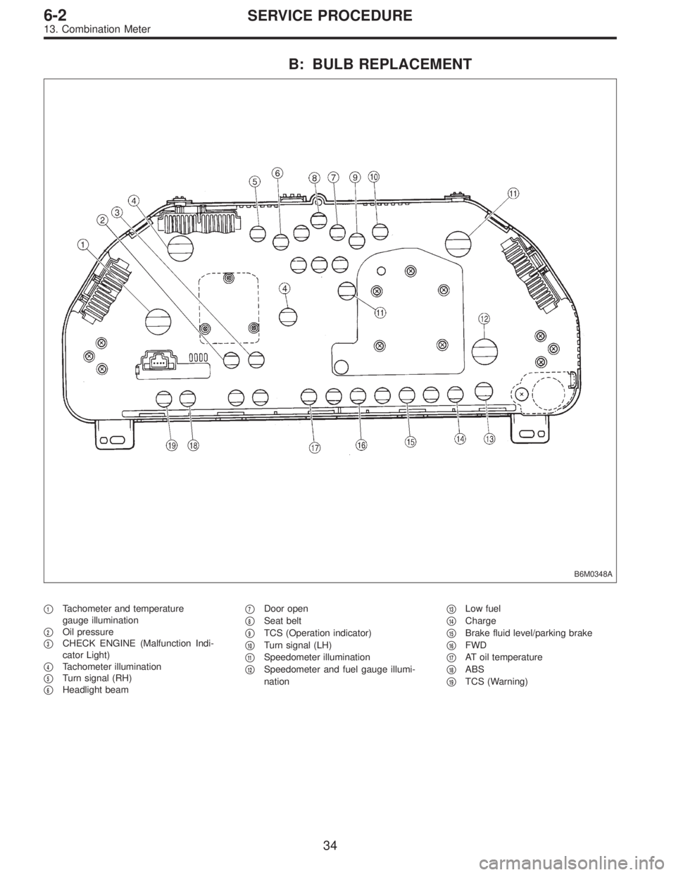
B: BULB REPLACEMENT
B6M0348A
�1Tachometer and temperature
gauge illumination
�
2Oil pressure
�
3CHECK ENGINE (Malfunction Indi-
cator Light)
�
4Tachometer illumination
�
5Turn signal (RH)
�
6Headlight beam�
7Door open
�
8Seat belt
�
9TCS (Operation indicator)
�
10Turn signal (LH)
�
11Speedometer illumination
�
12Speedometer and fuel gauge illumi-
nation�
13Low fuel
�
14Charge
�
15Brake fluid level/parking brake
�
16FWD
�
17AT oil temperature
�
18ABS
�
19TCS (Warning)
34
6-2SERVICE PROCEDURE
13. Combination Meter
Page 1712 of 2890
 Remove screws which secure meter visor.
2) Remove meter visor from instrument panel while dis-
connecting connectors.
3) Remove cr")
B6M0154A
B: REMOVAL AND INSTALLATION
1. CRUISE CONTROL MAIN SWITCH
1) Remove screws which secure meter visor.
2) Remove meter visor from instrument panel while dis-
connecting connectors.
3) Remove cruise control main switch from meter visor.
B6M0357A
2. CRUISE CONTROL COMMAND SWITCH
1) Remove screw which secures horn pad to the base of
steering wheel.
2) Remove horn pad from steering wheel while discon-
necting connector.
3) Disconnect connector of cruise control command
switch.
4) Remove screws which secure cruise control command
switch to steering wheel, and then remove command
switch.
WARNING:
Refer to 5-5 when removing or installing the module
from the airbag equipped model.
B6M0156
3. ACTUATOR
1) Loosen nut which secures cruise control cable end to
throttle cam, and then remove cable from engine throttle
cam.
2) Remove clip bands from cruise control cable.
CAUTION:
�Be careful not to apply excessive load to the wire
cable when adjusting and/or installing; otherwise, the
actuator may be deformed or damaged.
�Do not bend cable sharply with a radius less than
100 mm (3.94 in); otherwise, cable may bend
permanently, resulting in poor performance.
�When installing cable, be careful not to sharply bend
or pinch the inner cable; otherwise, the cable may
break.
48
6-2SERVICE PROCEDURE
21. Cruise Control
Page 1738 of 2890
B3M0289
1) Disconnect connector from vehicle speed sensor 2.
2) Measure resistance between terminals of vehicle speed
sensor 2.
Terminals / Specified resistance:
No. 1—No. 2 / 350—450Ω
B3M0256
WARNING:
Be careful not to be caught up by the running wheels.
3) Set the vehicle on free roller, or lift-up the vehicle and
support with safety stands.
4) Drive the vehicle at speed greater than 20 km/h (12
MPH).
5) Measure voltage between terminals of vehicle speed
sensor 2.
Terminals / Specified voltage:
No. 1—No.2/5V,min. (AC range)
B3M0257
�Using an oscilloscope:
(1) Turn ignition switch to OFF.
(2) Set oscilloscope to vehicle speed sensor 2.
(3) Drive the vehicle at speed greater than 20 km/h (12
MPH).
(4) Measure signal voltage.
Specified voltage (V): 5 V, min.
B3M0254A
74
6-2DIAGNOSTICS
3. Combination Meter
![SUBARU LEGACY 1996 Service Repair Manual 6. Turn Signal and Hazard Warning
Light
A: REMOVAL AND INSTALLATION
1. FRONT TURN SIGNAL LIGHT
Refer to 6-2 [W4B2] as for removal and installation of front
turn signal light.
NOTE:
The front turn sign](/manual-img/17/57433/w960_57433-1673.png "SUBARU LEGACY 1996 Service Repair Manual 6. Turn Signal and Hazard Warning
Light
A: REMOVAL AND INSTALLATION
1. FRONT TURN SIGNAL LIGHT
Refer to 6-2 [W4B2] as for removal and installation of front
turn signal light.
NOTE:
The front turn sign")
![SUBARU LEGACY 1996 Service Repair Manual B: DISASSEMBLY AND ASSEMBLY
1. COMBINATION SWITCH
Refer to 6-2 [W4C1] as for disassembly and assembly of
combination switch.
C: INSPECTION
1. COMBINATION SWITCH (ON-CAR)
1) Remove instrument panel low](/manual-img/17/57433/w960_57433-1674.png "SUBARU LEGACY 1996 Service Repair Manual B: DISASSEMBLY AND ASSEMBLY
1. COMBINATION SWITCH
Refer to 6-2 [W4C1] as for disassembly and assembly of
combination switch.
C: INSPECTION
1. COMBINATION SWITCH (ON-CAR)
1) Remove instrument panel low")
 Disconnect connector from vehicle speed sensor 2.
2) Measure resistance between terminals of vehicle speed
sensor 2.
Terminals / Specified resistance:
No. 1—No. 2 / 350—450Ω
B3M0256
W")