Page 599 of 2890
B2M0320
3) Install radiator brackets and tighten bolts.
4) Connect radiator main fan motor and sub fan motor
connectors.
B2M0137
5) Connect radiator inlet and outlet hoses.
6) Connect ATF cooler hoses. (AT model)
B2M0017
7) Install V-belt cover.
G6M0095
8) Connect ground cable to battery terminal.
15
2-5SERVICE PROCEDURE
4. Radiator
Page 600 of 2890
G2M0223
5. Radiator Cap
A: INSPECTION
1) Attach radiator cap to tester.
2) Increase pressure until tester gauge pointer stops.
Radiator cap is functioning properly if it holds the service
limit pressure for five to six seconds.
Standard pressure:
78—98 kPa (0.8—1.0 kg/cm
2,11—14 psi)
Service limit pressure:
69 kPa (0.7 kg/cm
2, 10 psi)
CAUTION:
Be sure to remove foreign matter and rust from the cap
in advance; otherwise, results of pressure test will be
incorrect.
G2M0263
6. Radiator Fan and Fan Motor
A: REMOVAL
1) Disconnect ground cable from battery terminal.
2) Disconnect connector of fan motor.
G2M0224
3) Remove reservoir tank.
B2M0308
4) Remove four bolts holding shroud to radiator.
16
2-5SERVICE PROCEDURE
5. Radiator Cap - 6. Radiator Fan and Fan Motor
Page 601 of 2890
G2M0223
5. Radiator Cap
A: INSPECTION
1) Attach radiator cap to tester.
2) Increase pressure until tester gauge pointer stops.
Radiator cap is functioning properly if it holds the service
limit pressure for five to six seconds.
Standard pressure:
78—98 kPa (0.8—1.0 kg/cm
2,11—14 psi)
Service limit pressure:
69 kPa (0.7 kg/cm
2, 10 psi)
CAUTION:
Be sure to remove foreign matter and rust from the cap
in advance; otherwise, results of pressure test will be
incorrect.
G2M0263
6. Radiator Fan and Fan Motor
A: REMOVAL
1) Disconnect ground cable from battery terminal.
2) Disconnect connector of fan motor.
G2M0224
3) Remove reservoir tank.
B2M0308
4) Remove four bolts holding shroud to radiator.
16
2-5SERVICE PROCEDURE
5. Radiator Cap - 6. Radiator Fan and Fan Motor
Page 602 of 2890
B2M0323
5) Remove radiator fan motor assembly.
6) Remove fan motor from shroud.
B: INSTALLATION
Installation is in the reverse order of removal procedures.
Do the following:
1) Before installing radiator fan motor, apply a coat of seal-
ant to threads and tighten nuts.
2) Make sure radiator fan does not come into contact with
shroud when installed.
3) After installation, make sure there is no unusual noise
or vibration when fan is rotated.
G6M0095
7. Engine Coolant Pipe
A: REMOVAL
1) Release fuel pressure.
2) Disconnect ground cable from the battery.
B2M0015A
3) Drain engine coolant completely.
B2M0160
4) Remove intake manifold.
17
2-5SERVICE PROCEDURE
6. Radiator Fan and Fan Motor - 7. Engine Coolant Pipe
Page 603 of 2890
B2M0323
5) Remove radiator fan motor assembly.
6) Remove fan motor from shroud.
B: INSTALLATION
Installation is in the reverse order of removal procedures.
Do the following:
1) Before installing radiator fan motor, apply a coat of seal-
ant to threads and tighten nuts.
2) Make sure radiator fan does not come into contact with
shroud when installed.
3) After installation, make sure there is no unusual noise
or vibration when fan is rotated.
G6M0095
7. Engine Coolant Pipe
A: REMOVAL
1) Release fuel pressure.
2) Disconnect ground cable from the battery.
B2M0015A
3) Drain engine coolant completely.
B2M0160
4) Remove intake manifold.
17
2-5SERVICE PROCEDURE
6. Radiator Fan and Fan Motor - 7. Engine Coolant Pipe
Page 605 of 2890
B2M0138
3) Connect heater inlet hose.
B2M0160
4) Install intake manifold.
G6M0095
5) Connect ground cable to battery terminal.
19
2-5SERVICE PROCEDURE
7. Engine Coolant Pipe
Page 609 of 2890

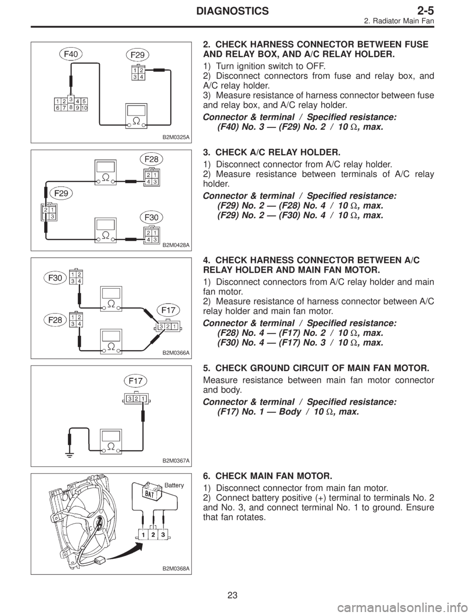
B2M0325A
2. CHECK HARNESS CONNECTOR BETWEEN FUSE
AND RELAY BOX, AND A/C RELAY HOLDER.
1) Turn ignition switch to OFF.
2) Disconnect connectors from fuse and relay box, and
A/C relay holder.
3) Measure resistance of harness connector between fuse
and relay box, and A/C relay holder.
Connector & terminal / Specified resistance:
(F40) No. 3—(F29) No. 2 / 10Ω, max.
B2M0428A
3. CHECK A/C RELAY HOLDER.
1) Disconnect connector from A/C relay holder.
2) Measure resistance between terminals of A/C relay
holder.
Connector & terminal / Specified resistance:
(F29) No. 2—(F28) No. 4 / 10Ω, max.
(F29) No. 2—(F30) No. 4 / 10Ω, max.
B2M0366A
4. CHECK HARNESS CONNECTOR BETWEEN A/C
RELAY HOLDER AND MAIN FAN MOTOR.
1) Disconnect connectors from A/C relay holder and main
fan motor.
2) Measure resistance of harness connector between A/C
relay holder and main fan motor.
Connector & terminal / Specified resistance:
(F28) No. 4—(F17) No. 2 / 10Ω, max.
(F30) No. 4—(F17) No. 3 / 10Ω, max.
B2M0367A
5. CHECK GROUND CIRCUIT OF MAIN FAN MOTOR.
Measure resistance between main fan motor connector
and body.
Connector & terminal / Specified resistance:
(F17) No. 1—Body / 10Ω, max.
B2M0368A
6. CHECK MAIN FAN MOTOR.
1) Disconnect connector from main fan motor.
2) Connect battery positive (+) terminal to terminals No. 2
and No. 3, and connect terminal No. 1 to ground. Ensure
that fan rotates.
23
2-5DIAGNOSTICS
2. Radiator Main Fan
Page 611 of 2890

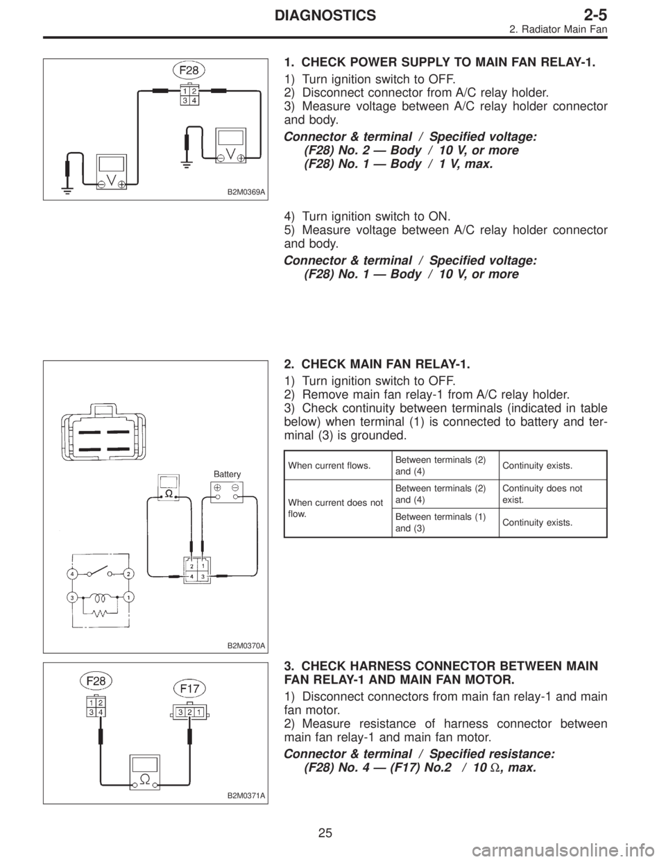
B2M0369A
1. CHECK POWER SUPPLY TO MAIN FAN RELAY-1.
1) Turn ignition switch to OFF.
2) Disconnect connector from A/C relay holder.
3) Measure voltage between A/C relay holder connector
and body.
Connector & terminal / Specified voltage:
(F28) No. 2—Body / 10 V, or more
(F28) No. 1—Body / 1 V, max.
4) Turn ignition switch to ON.
5) Measure voltage between A/C relay holder connector
and body.
Connector & terminal / Specified voltage:
(F28) No. 1—Body / 10 V, or more
B2M0370A
2. CHECK MAIN FAN RELAY-1.
1) Turn ignition switch to OFF.
2) Remove main fan relay-1 from A/C relay holder.
3) Check continuity between terminals (indicated in table
below) when terminal (1) is connected to battery and ter-
minal (3) is grounded.
When current flows.Between terminals (2)
and (4)Continuity exists.
When current does not
flow.Between terminals (2)
and (4)Continuity does not
exist.
Between terminals (1)
and (3)Continuity exists.
B2M0371A
3. CHECK HARNESS CONNECTOR BETWEEN MAIN
FAN RELAY-1 AND MAIN FAN MOTOR.
1) Disconnect connectors from main fan relay-1 and main
fan motor.
2) Measure resistance of harness connector between
main fan relay-1 and main fan motor.
Connector & terminal / Specified resistance:
(F28) No. 4—(F17) No.2 / 10Ω, max.
25
2-5DIAGNOSTICS
2. Radiator Main Fan