Page 294 of 2890

B2M0955A
B: INSTALLATION
CAUTION:
Leave fuel filler cap open when tightening nuts, to pre-
vent fuel from flowing out through fuel delivery and
return pipes. Close fuel filler cap after tightening nuts.
Installation is in the reverse order of removal. Do the fol-
lowing:
(1) Always use new gaskets.
(2) Ensure sealing portion is free from fuel or foreign
particles before installation.
(3) Tighten nuts in numerical sequence shown in Fig-
ure to specified torque.
Tightening torque:
4.4±1.5 N⋅m (0.45±0.15 kg-m, 3.3±1.1 ft-lb)
G6M0095
9. Fuel Tank Pressure Sensor (2200 cc
AWD Model)
A: REMOVAL AND INSTALLATION
1) Disconnect battery ground cable.
H2M1122B
2) Remove trims.
�4 door model:
Remove right trunk side trim.
B2M0927A
�Wagon model:
(1) Remove right rear quarter upper rear trim.
(2) Remove right strut cap.
(3) Remove right rear quarter pillar lower trim.
11
2-1SERVICE PROCEDURE
8. Fuel Temperature Sensor (2200 cc AWD Model) - 9. Fuel Tank Pressure Sensor (2200 cc AWD Model)
Page 295 of 2890
B2M0960
3) Disconnect connector from fuel tank pressure sensor.
4) Remove bolts which install fuel tank pressure sensor
bracket on body.
B2M0961
5) Disconnect hose from fuel tank pressure sensor.
6) Remove fuel tank pressure sensor from bracket.
7) Installation is in the reverse order of removal.
G6M0095
10. Pressure Control Solenoid Valve
(2200 cc AWD Model)
A: REMOVAL AND INSTALLATION
1) Disconnect battery ground cable.
2) Lift-up the vehicle.
B2M0962
3) Disconnect evaporation hoses from pressure control
valve.
4) Disconnect connector from pressure control valve.
B2M0963
5) Remove pressure control valve from bracket.
6) Installation is in the reverse order of removal.
12
2-1SERVICE PROCEDURE
9. Fuel Tank Pressure Sensor (2200 cc AWD Model) - 10. Pressure Control Solenoid Valve (2200 cc AWD Model)
Page 296 of 2890
B2M0960
3) Disconnect connector from fuel tank pressure sensor.
4) Remove bolts which install fuel tank pressure sensor
bracket on body.
B2M0961
5) Disconnect hose from fuel tank pressure sensor.
6) Remove fuel tank pressure sensor from bracket.
7) Installation is in the reverse order of removal.
G6M0095
10. Pressure Control Solenoid Valve
(2200 cc AWD Model)
A: REMOVAL AND INSTALLATION
1) Disconnect battery ground cable.
2) Lift-up the vehicle.
B2M0962
3) Disconnect evaporation hoses from pressure control
valve.
4) Disconnect connector from pressure control valve.
B2M0963
5) Remove pressure control valve from bracket.
6) Installation is in the reverse order of removal.
12
2-1SERVICE PROCEDURE
9. Fuel Tank Pressure Sensor (2200 cc AWD Model) - 10. Pressure Control Solenoid Valve (2200 cc AWD Model)
Page 297 of 2890
G6M0095
11. Vent Control Solenoid Valve (2200
cc AWD Model)
A: REMOVAL
1) Disconnect battery ground cable.
B2M0964
2) Lift-up the vehicle.
3) Remove canister.
4) Disconnect two hoses from air filter.
5) Disconnect connector from vent control solenoid valve.
H2M1469
6) Remove one bolt fixing bracket on the body.
B2M0965A
7) Remove two vacuum hoses from vent control solenoid
valve.
B2M0966
8) Remove one bolt fixing vent control solenoid valve on
bracket.
9) Remove vent control solenoid valve.
13
2-1SERVICE PROCEDURE
11. Vent Control Solenoid Valve (2200 cc AWD Model)
Page 298 of 2890
B2M0966
B: INSTALLATION
1) Install the bolt fixing vent control solenoid valve on
bracket.
B2M0965A
2) Install two vacuum hoses to vent control solenoid valve.
H2M1469
3) Install the bolt fixing bracket on the body.
Tightening torque:
25±7 N⋅m (2.5±0.7 kg-m, 18.1±5.1 ft-lb)
B2M0964
4) Connect connector to vent control solenoid valve.
5) Connect two hoses to air filter.
6) Install canister.
7) Let down the vehicle.
G6M0095
8) Connect battery ground cable.
14
2-1SERVICE PROCEDURE
11. Vent Control Solenoid Valve (2200 cc AWD Model)
Page 299 of 2890
G6M0095
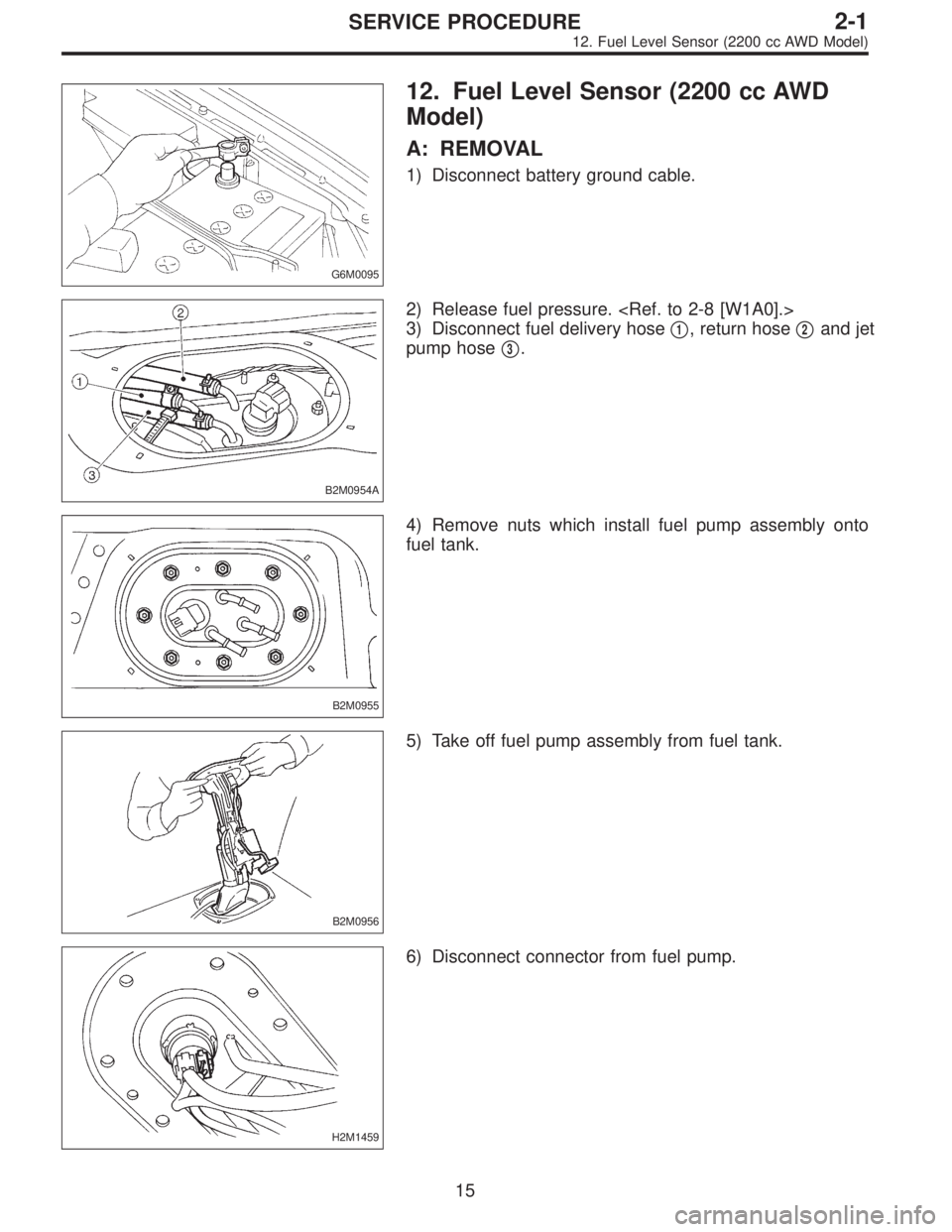
12. Fuel Level Sensor (2200 cc AWD
Model)
A: REMOVAL
1) Disconnect battery ground cable.
B2M0954A
2) Release fuel pressure.
3) Disconnect fuel delivery hose�
1, return hose�2and jet
pump hose�
3.
B2M0955
4) Remove nuts which install fuel pump assembly onto
fuel tank.
B2M0956
5) Take off fuel pump assembly from fuel tank.
H2M1459
6) Disconnect connector from fuel pump.
15
2-1SERVICE PROCEDURE
12. Fuel Level Sensor (2200 cc AWD Model)
Page 305 of 2890
 After warming-up the engine, turn ignition switch to
OFF.
2) Make sure that the battery is fully charged.
3) Remove all the spark plugs.
4) Dis")
4. Engine Compression
A: MEASUREMENT
1. 2200 cc MODEL
1) After warming-up the engine, turn ignition switch to
OFF.
2) Make sure that the battery is fully charged.
3) Remove all the spark plugs.
4) Disconnect connectors from fuel injectors.
5) Fully open throttle valve.
6) Check the starter motor for satisfactory performance
and operation.
G2M0098
7) Hold the compression gauge tight against the spark
plug hole.
CAUTION:
When using a screw-in type compression gauge, the
screw (put into cylinder head spark plug hole) should
be less than 18 mm (0.71 in) long.
8) Crank the engine by means of the starter motor, and
read the maximum value on the gauge when the pointer is
steady.
9) Perform at least two measurements per cylinder, and
make sure that the values are correct.
Compression (200—300 rpm and fully open throttle):
Standard
1,079—1,275 kPa
(11.0—13.0 kg/cm
2, 156—185 psi)
Limit
883 kPa (9.0 kg/cm
2, 128 psi)
Difference between cylinders
196 kPa (2.0 kg/cm
2, 28 psi)
2. 2500 cc MODEL
CAUTION:
After warming-up, engine becomes very hot. Be care-
ful not to burn yourself during measurement.
1) After warming-up the engine, turn ignition switch to
OFF.
2) Make sure that the battery is fully charged.
3) Remove all the spark plugs.
[W3E0].>
4) Disconnect connectors from fuel injectors.
4
2-2
4. Engine Compression
Page 319 of 2890
 Before disassembling engine, place it on ST3.
ST1 498457000 ENGINE STAND ADAPTER RH
ST2 498457100 ENGINE STAND ADAPTER LH
ST3 499817000 ENGINE STAND
2) All parts shou")
G2M0106
1. General Precautions
1) Before disassembling engine, place it on ST3.
ST1 498457000 ENGINE STAND ADAPTER RH
ST2 498457100 ENGINE STAND ADAPTER LH
ST3 499817000 ENGINE STAND
2) All parts should be thoroughly cleaned, paying special
attention to the engine oil passages, pistons and bearings.
3) Rotating parts and sliding parts such as piston, bearing
and gear should be coated with oil prior to assembly.
4) Be careful not to let oil, grease or coolant contact the
timing belt, clutch disc and flywheel.
5) All removed parts, if to be reused, should be reinstalled
in the original positions and directions.
6) Gaskets and lock washers must be replaced with new
ones. Liquid gasket should be used where specified to
prevent leakage.
7) Bolts, nuts and washers should be replaced with new
ones as required.
8) Even if necessary inspections have been made in
advance, proceed with assembly work while making
rechecks.
2. Hydraulic Lash Adjuster
A: INSPECTION
1) Disconnect blow-by hose from rocker cover.
2) Remove spark plug cap.
B2M0413A
3) Remove left and right rocker covers.
CAUTION:
Before removing left rocker cover, disconnect battery
cables and generator cable.
11
2-3SERVICE PROCEDURE
1. General Precautions - 2. Hydraulic Lash Adjuster
 Disconnect connector from fuel tank pressure sensor.
4) Remove bolts which install fuel tank pressure sensor
bracket on body.
B2M0961
5) Disconnect hose from fuel tank pressure sensor.
6) R")
 Disconnect connector from fuel tank pressure sensor.
4) Remove bolts which install fuel tank pressure sensor
bracket on body.
B2M0961
5) Disconnect hose from fuel tank pressure sensor.
6) R")
![SUBARU LEGACY 1996 Service Repair Manual G6M0095
11. Vent Control Solenoid Valve (2200
cc AWD Model)
A: REMOVAL
1) Disconnect battery ground cable.
B2M0964
2) Lift-up the vehicle.
3) Remove canister. <Ref. to 2-1 [W3A2].>
4) Disconnect two h](/manual-img/17/57433/w960_57433-296.png "SUBARU LEGACY 1996 Service Repair Manual G6M0095
11. Vent Control Solenoid Valve (2200
cc AWD Model)
A: REMOVAL
1) Disconnect battery ground cable.
B2M0964
2) Lift-up the vehicle.
3) Remove canister. <Ref. to 2-1 [W3A2].>
4) Disconnect two h")
 Install the bolt fixing vent control solenoid valve on
bracket.
B2M0965A
2) Install two vacuum hoses to vent control solenoid valve.
H2M1469
3) Install the bolt fixing brack")