Page 2554 of 2890

10AB22CHECK POOR CONTACT IN CONNEC-
TOR BETWEEN ABSCM AND HYDRAU-
LIC UNIT.
: Is there poor contact in connector between
ABSCM and hydraulic unit?
: Repair connector.
: Go to step10AB23.
10AB23
CHECK ABSCM.
1) Connect all connectors.
2) Erase the memory.
3) Perform inspection mode.
4) Read out the trouble code.
: Is the same trouble code as in the current
diagnosis still being output?
: Replace ABSCM.
: Go to next.
: Are other trouble codes being output?
: Proceed with the diagnosis corresponding to the
trouble code.
: A temporary poor contact.
B4M0880B
10AB24CHECK BATTERY SHORT OF SOLENOID
VA LV E .
1) Turn ignition switch to OFF.
2) Disconnect connectors (ABS1, F9) from hydraulic unit.
3) Disconnect connector from ABSCM.
4) Turn ignition switch to ON.
5) Measure voltage between hydraulic unit connector and
chassis ground.
: Connector & terminal
To (F9) No. 4 (+)—Chassis ground (�)
Is voltage 0 V?
: Go to next step.
: Replace hydraulic unit and check all fuses.
214
4-4cBRAKES [ABS 5.3 TYPE]
10. Diagnostics Chart with Select Monitor
Page 2555 of 2890
 Turn ignition switch to OFF.
7) Measure voltage between hydraulic unit connector and
chassis ground.
: Connector & terminal
To (F63) No. 4 (+)—Chassis ground (�)
Is voltage 0 V?
: Go to step10AB2")
6) Turn ignition switch to OFF.
7) Measure voltage between hydraulic unit connector and
chassis ground.
: Connector & terminal
To (F63) No. 4 (+)—Chassis ground (�)
Is voltage 0 V?
: Go to step10AB25.
: Replace hydraulic unit and check all fuses.
B4M0881A
10AB25
CHECK BATTERY SHORT OF HARNESS.
1) Turn ignition switch to ON.
2) Measure voltage between ABSCM connector and chas-
sis ground.
: Connector & terminal
(F49) No. 30 (+)—Chassis ground (�)
(F49) No. 24 (+)—Chassis ground (�)
(F49) No. 23 (+)—Chassis ground (�)
(F49) No. 31 (+)—Chassis ground (�)
(F49) No. 3 (+)—Chassis ground (�)
(F49) No. 51 (+)—Chassis ground (�)
(F49) No. 50 (+)—Chassis ground (�)
(F49) No. 4 (+)—Chassis ground (�)
Is voltage 0 V?
: Go to next step.
: Repair harness between hydraulic unit and
ABSCM and check all fuses.
3) Turn ignition switch to OFF.
4) Measure voltage between ABSCM connector and chas-
sis ground.
: Connector & terminal
(F49) No. 30 (+)—Chassis ground (�)
(F49) No. 24 (+)—Chassis ground (�)
(F49) No. 23 (+)—Chassis ground (�)
(F49) No. 31 (+)—Chassis ground (�)
(F49) No. 3 (+)—Chassis ground (�)
(F49) No. 51 (+)—Chassis ground (�)
(F49) No. 50 (+)—Chassis ground (�)
(F49) No. 4 (+)—Chassis ground (�)
Is voltage 0 V?
: Go to step10AB26.
: Repair harness between hydraulic unit and
ABSCM and check all fuses.
215
4-4cBRAKES [ABS 5.3 TYPE]
10. Diagnostics Chart with Select Monitor
Page 2556 of 2890
10AB26
CHECK ABSCM.
1) Connect all connectors.
2) Erase the memory.
3) Perform inspection mode.
4) Read out the trouble code.
: Is the same trouble code as in the current
diagnosis still being output?
: Replace ABSCM.
: Go to next.
: Are other trouble codes being output?
: Proceed with the diagnosis corresponding to the
trouble code.
: A temporary poor contact.
216
4-4cBRAKES [ABS 5.3 TYPE]
10. Diagnostics Chart with Select Monitor
Page 2557 of 2890
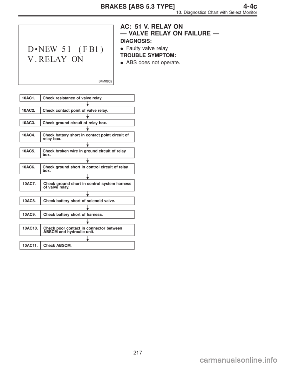
B4M0802
AC: 51 V. RELAY ON
—VALVE RELAY ON FAILURE—
DIAGNOSIS:
�Faulty valve relay
TROUBLE SYMPTOM:
�ABS does not operate.
10AC1.Check resistance of valve relay.
10AC2.Check contact point of valve relay.
10AC3.Check ground circuit of relay box.
10AC4.Check battery short in contact point circuit of
relay box.
10AC5.Check broken wire in ground circuit of relay
box.
10AC6.Check ground short in control circuit of relay
box.
10AC7.Check ground short in control system harness
of valve relay.
10AC8.Check battery short of solenoid valve.
10AC9.Check battery short of harness.
10AC10.Check poor contact in connector between
ABSCM and hydraulic unit.
10AC11.Check ABSCM.
�
�
�
�
�
�
�
�
�
�
217
4-4cBRAKES [ABS 5.3 TYPE]
10. Diagnostics Chart with Select Monitor
Page 2558 of 2890
WIRING DIAGRAM:
B4M1048
B4M0858A
10AC1
CHECK RESISTANCE OF VALVE RELAY.
1) Turn ignition switch to OFF.
2) Remove valve relay from relay box.
3) Measure resistance between valve relay terminals.
: Terminals
No. 85—No. 86
Is resistance 103±10Ω?
: Go to step10AC2.
: Replace valve relay.
218
4-4cBRAKES [ABS 5.3 TYPE]
10. Diagnostics Chart with Select Monitor
Page 2559 of 2890
B4M0811A
10AC2CHECK CONTACT POINT OF VALVE
RELAY.
1) Connect battery to valve relay terminals No. 85 and No.
86.
2) Measure resistance between valve relay terminals.
: Terminals
No. 30—No. 87
Is resistance less than 0.5Ω?
: Go to next.
: Replace valve relay.
: Terminals
No. 30—No. 87a
Is resistance more than 1 MΩ?
: Go to next step.
: Replace valve relay.
B4M0798A
3) Disconnect battery from valve relay terminals.
4) Measure resistance between valve relay terminals.
: Terminals
No. 30—No. 87
Is resistance more than 1 MΩ?
: Go to next.
: Replace valve relay.
: Terminals
No. 30—No. 87a
Is resistance less than 0.5Ω?
: Go to step10AC3.
: Replace valve relay.
219
4-4cBRAKES [ABS 5.3 TYPE]
10. Diagnostics Chart with Select Monitor
Page 2560 of 2890
 Disconnect connector (F50) from relay box.
2) Measure resistance between relay box connector and
chassis ground.
: Connector & terminal
(F50) No. 3�")
B4M0863B
10AC3CHECK GROUND CIRCUIT OF RELAY
BOX.
1) Disconnect connector (F50) from relay box.
2) Measure resistance between relay box connector and
chassis ground.
: Connector & terminal
(F50) No. 3—Chassis ground
Is resistance less than 0.5Ω?
: Go to step10AC4.
: Repair relay box ground harness.
B4M0867A
10AC4CHECK BATTERY SHORT IN CONTACT
POINT CIRCUIT OF RELAY BOX.
1) Disconnect connector from ABSCM.
2) Disconnect connector (ABS1) from hydraulic unit.
3) Turn ignition switch to ON.
4) Measure voltage between hydraulic unit connector and
chassis ground.
: Connector & terminal
(ABS1) No. 2 (+)—Chassis ground (�)
Is voltage 0 V?
: Go to next step.
: Replace relay box. Check fuse No. 19 and SBF6.
5) Turn ignition switch to OFF.
6) Measure voltage between hydraulic unit connector and
chassis ground.
: Connector & terminal
(ABS1) No. 2 (+)—Chassis ground (�)
Is voltage 0 V?
: Go to step10AC5.
: Replace relay box. Check fuse No. 9 and SBF6.
220
4-4cBRAKES [ABS 5.3 TYPE]
10. Diagnostics Chart with Select Monitor
Page 2561 of 2890
 No. 3—Valve relay i")
B4M0869B
10AC5CHECK BROKEN WIRE IN GROUND CIR-
CUIT OF RELAY BOX.
Measure resistance between relay box connector and
valve relay installing point.
: Connector & terminal
To (F50) No. 3—Valve relay installing point
No. 87a
Is resistance less than 0.5Ω?
: Go to step10AC6.
: Replace relay box.
B4M0872B
10AC6CHECK GROUND SHORT IN CONTROL
CIRCUIT OF RELAY BOX.
1) Install valve relay to relay box.
2) Measure resistance between relay box connector and
chassis ground.
: Connector & terminal
To (F50) No. 1—Chassis ground
Is resistance more than 1 MΩ?
: Go to step10AC7.
: Replace relay box and check all fuses.
B4M0875A
10AC7CHECK GROUND SHORT IN CONTROL
SYSTEM HARNESS OF VALVE RELAY.
Measure resistance between ABSCM connector and chas-
sis ground.
: Connector & terminal
(F49) No. 27—Chassis ground
Is resistance more than 1 MΩ?
: Go to step10AC8.
: Repair harness between ABSCM and relay box.
Check fuse No. 18.
221
4-4cBRAKES [ABS 5.3 TYPE]
10. Diagnostics Chart with Select Monitor
 Connect all connectors.
2) Erase the memory.
3) Perform inspection mode.
4) Read out the trouble code.
: Is the same trouble code as in the current
diagnosis still being output?")
 Turn ignition switch to OFF.
2) Remove valve relay from relay box.
3) Measure resistance between valve relay terminals.
: Ter")
 Connect battery to valve relay terminals No. 85 and No.
86.
2) Measure resistance between valve relay terminals.
: Terminals
No. 30—No. 87
Is res")