Page 774 of 2890
6) Oil seal
Replace the oil seal if the lip is deformed, hardened,
damaged, worn, or defective in any way.
7) O-ring
Replace the O-ring if the sealing face is deformed,
hardened, damaged, worn, or defective in any way.
8) Gearshift mechanism
Repair or replace the gearshift mechanism if excessively
worn, bent, or defective in any way.
G3M0521
9) Differential gear
Repair or replace the differential gear in the following
cases:
(1) The hypoid drive gear and drive pinion shaft tooth
surface are damaged, excessively worn, or seized.
(2) The roller bearing on the drive pinion shaft has a
worn or damaged roller path.
(3) There is damage, wear, or seizure of the differen-
tial bevel pinion, differential bevel gear, washer, pinion
shaft, and straight pin.
(4) The differential case has worn or damaged sliding
surfaces.
18
3-1SERVICE PROCEDURE
1. General
Page 775 of 2890
2. Transfer Case and Extension (AWD
Model)
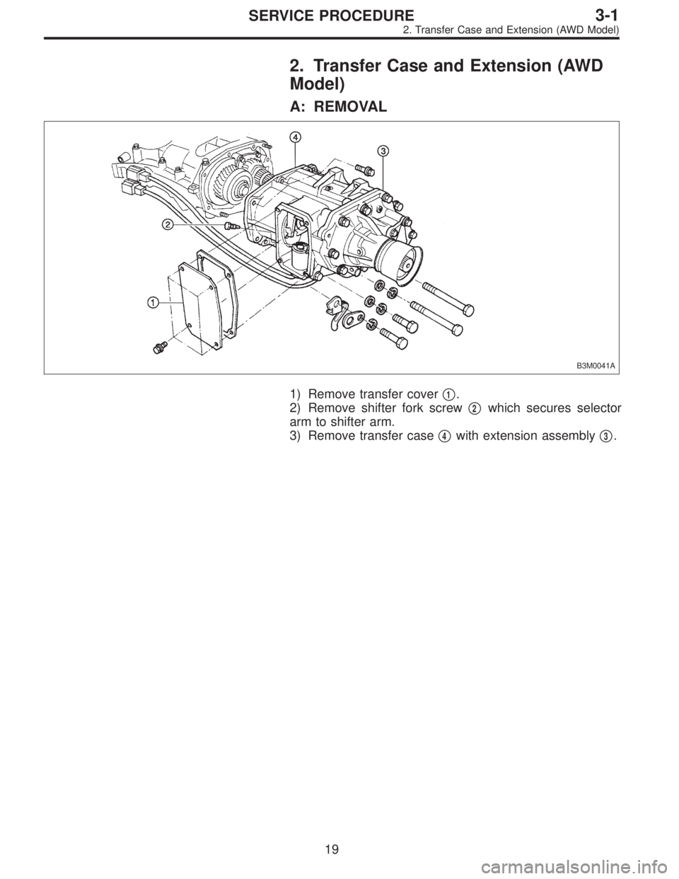
A: REMOVAL
B3M0041A
1) Remove transfer cover�1.
2) Remove shifter fork screw�
2which secures selector
arm to shifter arm.
3) Remove transfer case�
4with extension assembly�3.
19
3-1SERVICE PROCEDURE
2. Transfer Case and Extension (AWD Model)
Page 776 of 2890
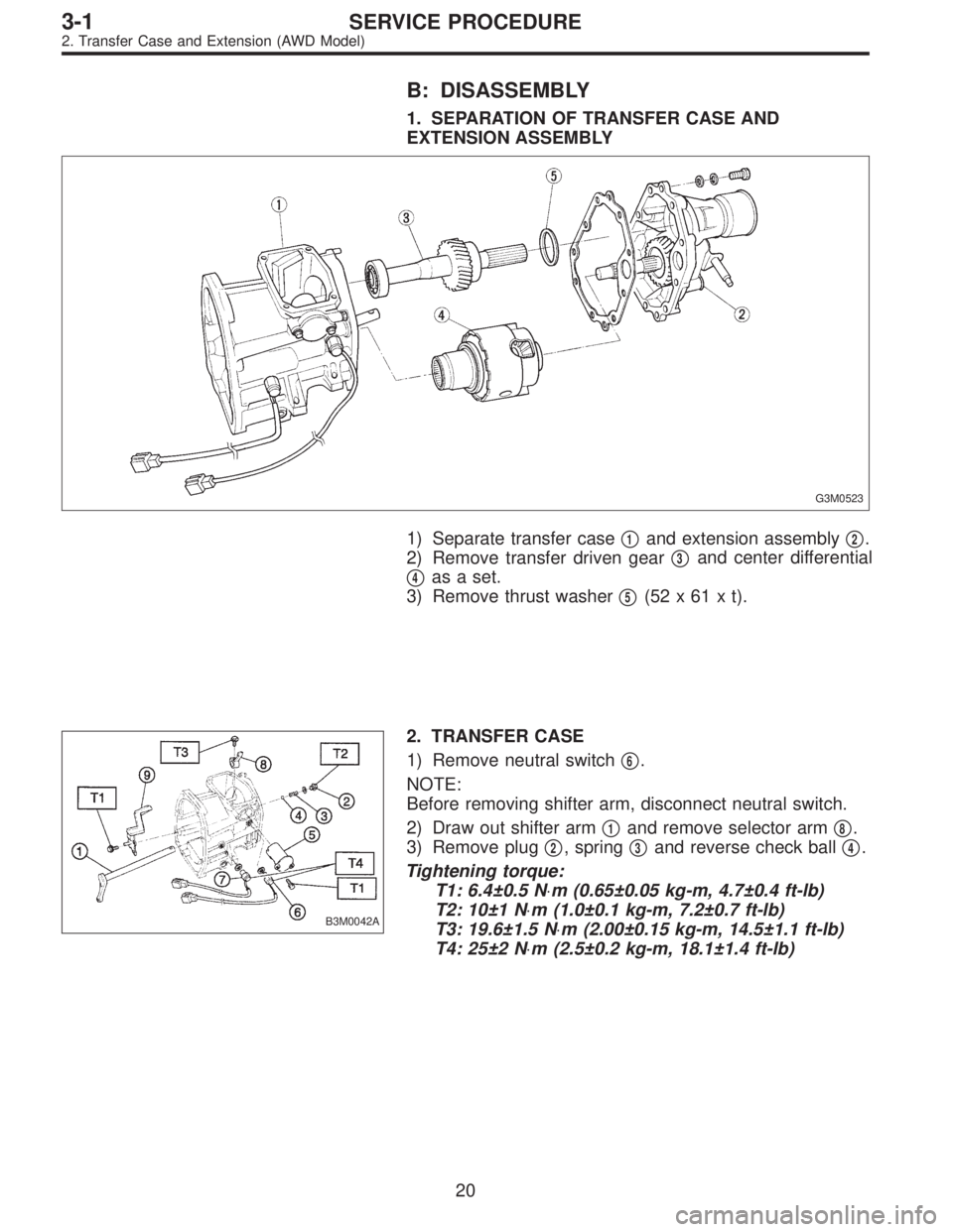
B: DISASSEMBLY
1. SEPARATION OF TRANSFER CASE AND
EXTENSION ASSEMBLY
G3M0523
1) Separate transfer case�1and extension assembly�2.
2) Remove transfer driven gear�
3and center differential
�
4as a set.
3) Remove thrust washer�
5(52x61xt).
B3M0042A
2. TRANSFER CASE
1) Remove neutral switch�
6.
NOTE:
Before removing shifter arm, disconnect neutral switch.
2) Draw out shifter arm�
1and remove selector arm�8.
3) Remove plug�
2, spring�3and reverse check ball�4.
Tightening torque:
T1: 6.4±0.5 N⋅m (0.65±0.05 kg-m, 4.7±0.4 ft-lb)
T2: 10±1 N⋅m (1.0±0.1 kg-m, 7.2±0.7 ft-lb)
T3: 19.6±1.5 N⋅m (2.00±0.15 kg-m, 14.5±1.1 ft-lb)
T4: 25±2 N⋅m (2.5±0.2 kg-m, 18.1±1.4 ft-lb)
20
3-1SERVICE PROCEDURE
2. Transfer Case and Extension (AWD Model)
Page 778 of 2890
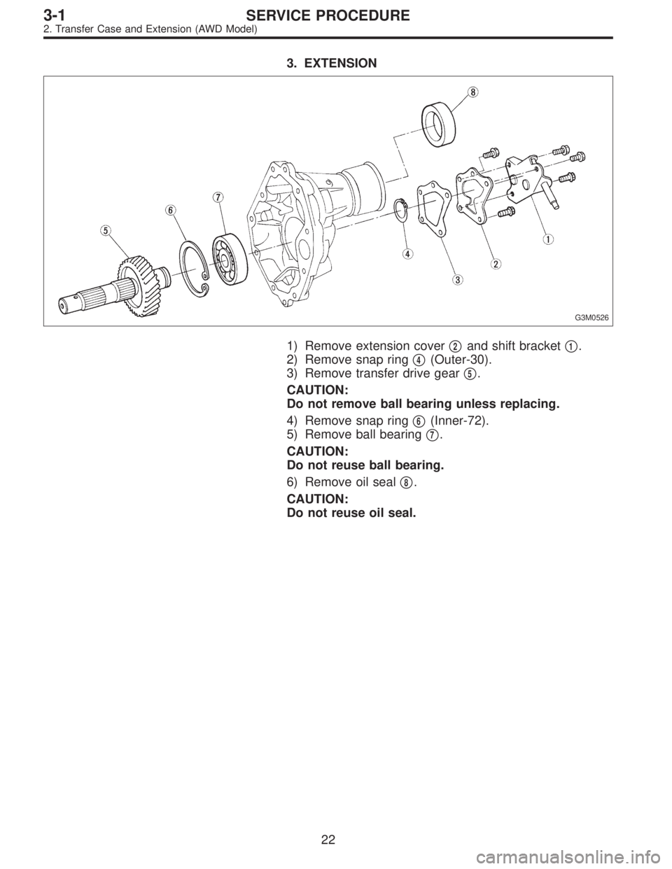
3. EXTENSION
G3M0526
1) Remove extension cover�2and shift bracket�1.
2) Remove snap ring�
4(Outer-30).
3) Remove transfer drive gear�
5.
CAUTION:
Do not remove ball bearing unless replacing.
4) Remove snap ring�
6(Inner-72).
5) Remove ball bearing�
7.
CAUTION:
Do not reuse ball bearing.
6) Remove oil seal�
8.
CAUTION:
Do not reuse oil seal.
22
3-1SERVICE PROCEDURE
2. Transfer Case and Extension (AWD Model)
Page 780 of 2890
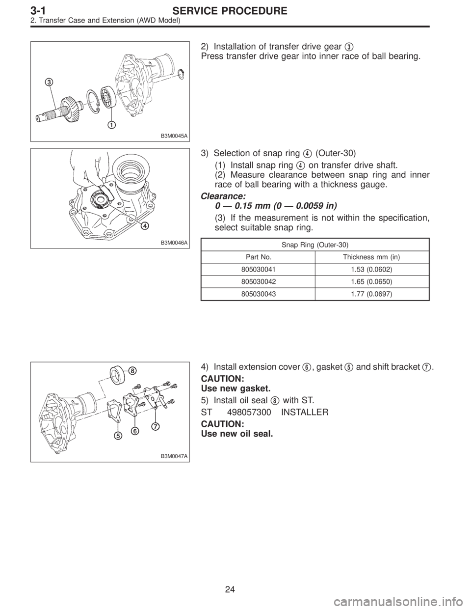
B3M0045A
2) Installation of transfer drive gear�3
Press transfer drive gear into inner race of ball bearing.
B3M0046A
3) Selection of snap ring�4(Outer-30)
(1) Install snap ring�
4on transfer drive shaft.
(2) Measure clearance between snap ring and inner
race of ball bearing with a thickness gauge.
Clearance:
0—0.15 mm (0—0.0059 in)
(3) If the measurement is not within the specification,
select suitable snap ring.
Snap Ring (Outer-30)
Part No. Thickness mm (in)
805030041 1.53 (0.0602)
805030042 1.65 (0.0650)
805030043 1.77 (0.0697)
B3M0047A
4) Install extension cover�6, gasket�5and shift bracket�7.
CAUTION:
Use new gasket.
5) Install oil seal�
8with ST.
ST 498057300 INSTALLER
CAUTION:
Use new oil seal.
24
3-1SERVICE PROCEDURE
2. Transfer Case and Extension (AWD Model)
Page 782 of 2890
 Installation of shifter arm�1and selector arm�8
Install shifter arm into the partition from the front while
inserting selector arm into the opening in reverse check
sleeve. Pass shaft thro")
B3M0042A
2) Installation of shifter arm�1and selector arm�8
Install shifter arm into the partition from the front while
inserting selector arm into the opening in reverse check
sleeve. Pass shaft through hole in selector arm until its end
comes out of the rear of transfer case.
NOTE:
Apply a coat of gear oil to shifter arm. Also make sure oil
seal is positioned properly.
Tightening torque:
T1: 6.4±0.5 N⋅m (0.65±0.05 kg-m, 4.7±0.4 ft-lb)
T2: 10±1 N⋅m (1.0±0.1 kg-m, 7.2±0.7 ft-lb)
T3: 19.6±1.5 N⋅m (2.00±0.15 kg-m, 14.5±1.1 ft-lb)
T4: 25±2 N⋅m (2.5±0.2 kg-m, 18.1±1.4 ft-lb)
B3M0049A
3. COMBINATION OF TRANSFER CASE AND
EXTENSION ASSEMBLY
1) Install center differential�
1and transfer driven gear�2
into transfer case.
Tightening torque:
T: 37±3 N⋅m (3.8±0.3 kg-m, 27.5±2.2 ft-lb)
B3M0050A
2) Selection of thrust washer (52 x 61 x t)
(1) Measure height“W”between transfer case and ball
bearing on the transfer driven gear�
3.
26
3-1SERVICE PROCEDURE
2. Transfer Case and Extension (AWD Model)
Page 784 of 2890

T1: 15.7±1.5 (1.6±0.15, 11.6±1.1)
T2: 19.6±1.5 (2.00±0.15, 14.5±1.1)
T3: 24.5±2.0 (2.50±0.20, 18.1±1.4)
1) Install transfer cas")
D: INSTALLATION
B3M0053A
Tightening torque: N⋅m (kg-m, ft-lb)
T1: 15.7±1.5 (1.6±0.15, 11.6±1.1)
T2: 19.6±1.5 (2.00±0.15, 14.5±1.1)
T3: 24.5±2.0 (2.50±0.20, 18.1±1.4)
1) Install transfer case�2with extension assembly�1.
2) Secure selector arm to shifter arm with shifter fork
screw�
3. Shifter arm should be caught by pawl of rod.
Selector arm must be engaged with reverse check sleeve
assembly.
3) Adjustment of neutral position
(1) Shift gear into 3rd gear position.
(2) Shifter arm turns lightly toward the 1st/2nd gear
side but heavily toward the reverse gear side because
of the function of the return spring, until arm contacts
the stopper.
(3) Make adjustment so that the heavy stroke (reverse
side) is a little more than the light stroke (1st/2nd side).
(4) To adjust, remove bolts holding reverse check
sleeve assembly�
4to the case, move sleeve assem-
bly outward, and place adjustment shim (0 to 1 ea.)
between sleeve assembly and case to adjust the clear-
ance.
28
3-1SERVICE PROCEDURE
2. Transfer Case and Extension (AWD Model)
Page 785 of 2890
.
Adjustment shim
Part No. Thickness mm (in)
32190AA000 0.15 (0.0059)
32190AA010 0.30 (0.0118)
�When shim is removed, the neutral position w")
CAUTION:
Be careful not to break O-ring when placing shim(s).
Adjustment shim
Part No. Thickness mm (in)
32190AA000 0.15 (0.0059)
32190AA010 0.30 (0.0118)
�When shim is removed, the neutral position will move
closer to reverse; when shim is added, the neutral position
will move closer to 1st gear.
�If shims alone cannot adjust the clearance, replace
reverse accent shaft and re-adjust.
Reverse accent shaft
Part No. Mark Remarks
32188AA040 1 Neutral position is closer to 1st gear.
32188AA011No mark
or 2Standard
32188AA050 3Neutral position is closer to reverse
gear.
B3M0054A
4) Reverse check plate�5adjustment
Shift shifter arm to“5th”and then to reverse to see if
reverse check mechanism operates properly. Also check to
see if arm returns to neutral when released from the
reverse position. If arm does not return properly, replace
reverse check plate.
Reverse check plate
Part No.�
A: No. AngleθRemarks
32189AA000 0 28°Arm stops closer to 5th
gear.
32189AA010 1 31°Arm stops closer to 5th
gear.
32189AA020 2 34°Arm stops in the center.
32189AA030 3 37°Arm stops closer to reverse
gear.
32189AA040 4 40°Arm stops closer to reverse
gear.
B3M0055A
5) Install transfer�6cover and gasket.
6) Connect each connector�
7.
29
3-1SERVICE PROCEDURE
2. Transfer Case and Extension (AWD Model)
 Oil seal
Replace the oil seal if the lip is deformed, hardened,
damaged, worn, or defective in any way.
7) O-ring
Replace the O-ring if the sealing face is deformed,
hardened, damaged, worn, or def")