Page 2455 of 2890
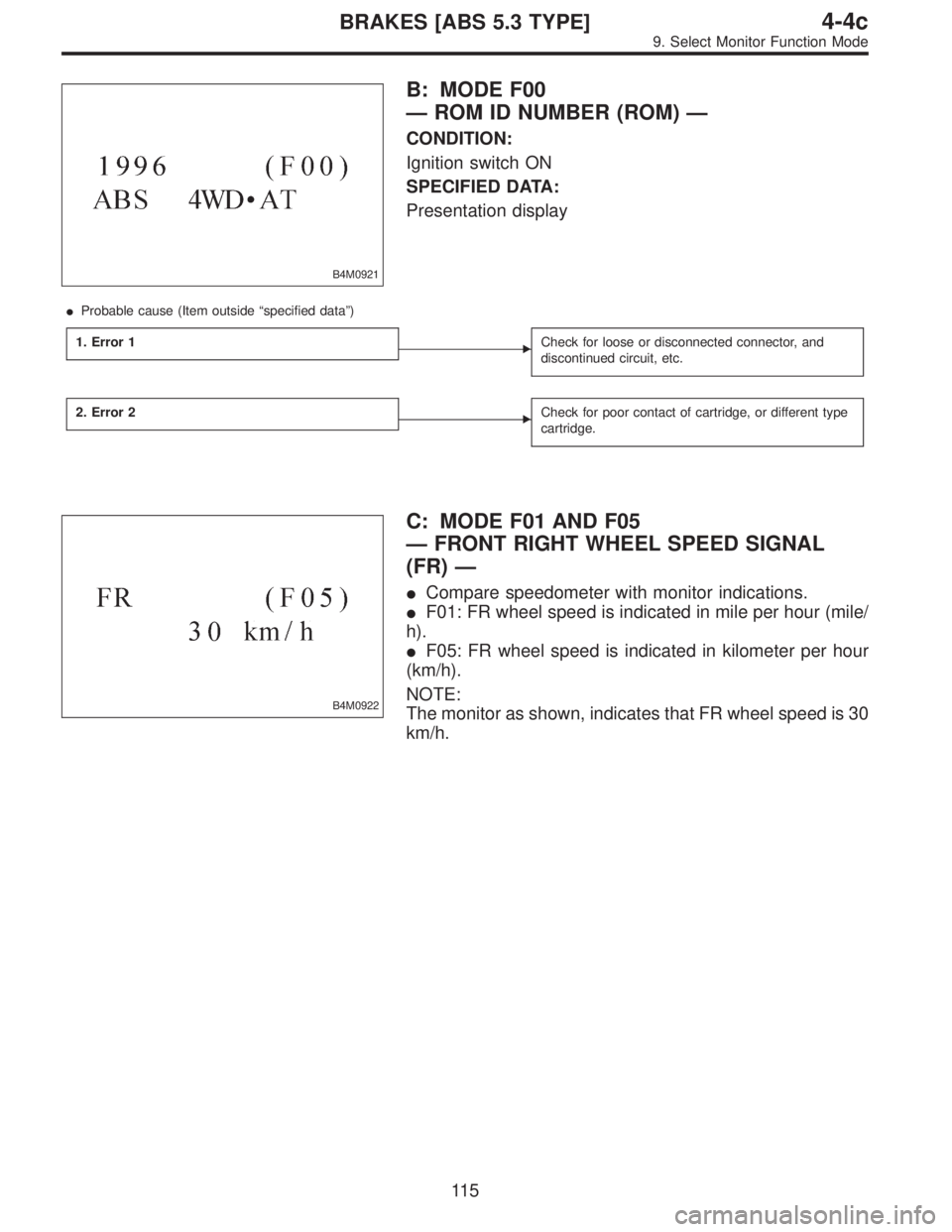
B4M0921
B: MODE F00
—ROM ID NUMBER (ROM)—
CONDITION:
Ignition switch ON
SPECIFIED DATA:
Presentation display
�Probable cause (Item outside“specified data”)
1. Error 1
�Check for loose or disconnected connector, and
discontinued circuit, etc.
2. Error 2�Check for poor contact of cartridge, or different type
cartridge.
B4M0922
C: MODE F01 AND F05
—FRONT RIGHT WHEEL SPEED SIGNAL
(FR)—
�Compare speedometer with monitor indications.
�F01: FR wheel speed is indicated in mile per hour (mile/
h).
�F05: FR wheel speed is indicated in kilometer per hour
(km/h).
NOTE:
The monitor as shown, indicates that FR wheel speed is 30
km/h.
11 5
4-4cBRAKES [ABS 5.3 TYPE]
9. Select Monitor Function Mode
Page 2456 of 2890
B4M0923
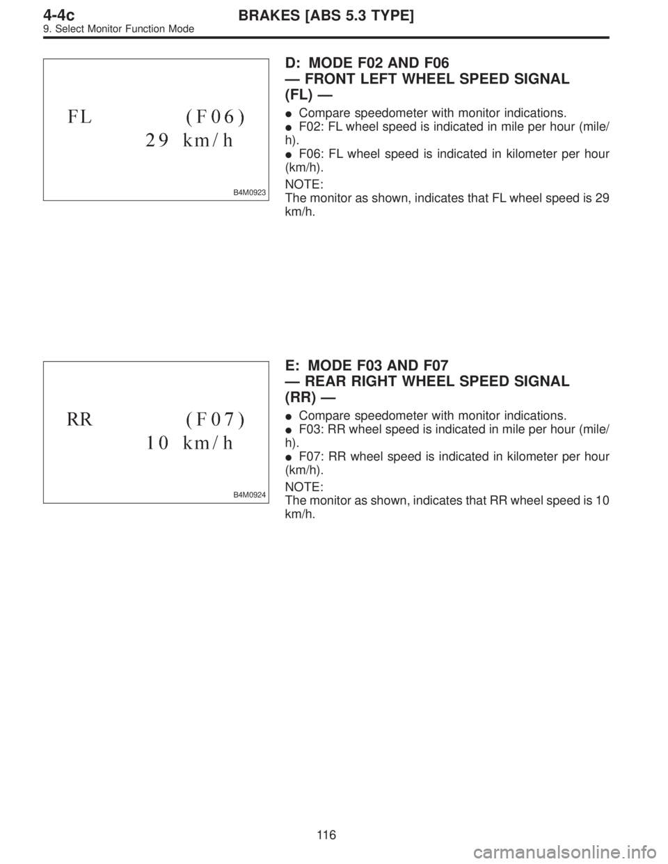
D: MODE F02 AND F06
—FRONT LEFT WHEEL SPEED SIGNAL
(FL)—
�Compare speedometer with monitor indications.
�F02: FL wheel speed is indicated in mile per hour (mile/
h).
�F06: FL wheel speed is indicated in kilometer per hour
(km/h).
NOTE:
The monitor as shown, indicates that FL wheel speed is 29
km/h.
B4M0924
E: MODE F03 AND F07
—REAR RIGHT WHEEL SPEED SIGNAL
(RR)—
�Compare speedometer with monitor indications.
�F03: RR wheel speed is indicated in mile per hour (mile/
h).
�F07: RR wheel speed is indicated in kilometer per hour
(km/h).
NOTE:
The monitor as shown, indicates that RR wheel speed is 10
km/h.
11 6
4-4cBRAKES [ABS 5.3 TYPE]
9. Select Monitor Function Mode
Page 2457 of 2890
B4M0925
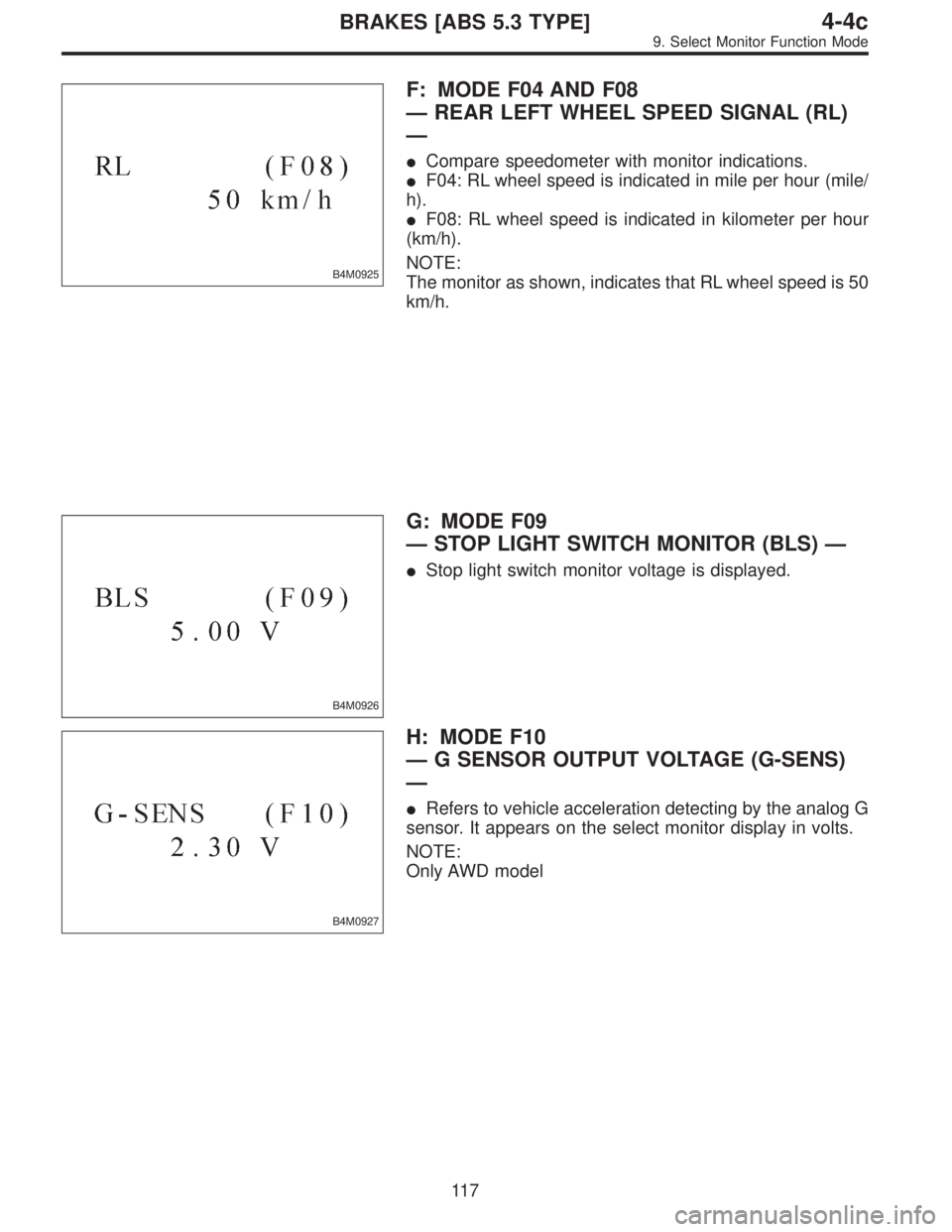
F: MODE F04 AND F08
—REAR LEFT WHEEL SPEED SIGNAL (RL)
—
�Compare speedometer with monitor indications.
�F04: RL wheel speed is indicated in mile per hour (mile/
h).
�F08: RL wheel speed is indicated in kilometer per hour
(km/h).
NOTE:
The monitor as shown, indicates that RL wheel speed is 50
km/h.
B4M0926
G: MODE F09
—STOP LIGHT SWITCH MONITOR (BLS)—
�Stop light switch monitor voltage is displayed.
B4M0927
H: MODE F10
—G SENSOR OUTPUT VOLTAGE (G-SENS)
—
�Refers to vehicle acceleration detecting by the analog G
sensor. It appears on the select monitor display in volts.
NOTE:
Only AWD model
11 7
4-4cBRAKES [ABS 5.3 TYPE]
9. Select Monitor Function Mode
Page 2458 of 2890
LED No. Signal name Display
1 Stop light switch B1
2 Valve relay signal VR
3 Motor relay signal MR
4 AT ABS signal AT
5——
6 ABS warning light AW
7 Valve relay monitor VM
8 Motor relay monitor MM
9 CCM signal CM
10——
B1 VR MR AT—
AW VM MM CM—
1
2345
678910
I: MODE FA0
—ON↔OFF SIGNAL—
Requirement for LED“ON”
LED No. 1 Stop light switch is turned ON. (With brake
pedal depressed.)
LED No. 2 Valve relay is turned OFF.
LED No. 3 Motor relay is turned ON.
LED No. 4 ABS control operates.
LED No. 6 ABS warning light is ON.
LED No. 7 Valve relay is turned OFF.
LED No. 8 Motor relay is turned ON.
LED No. 9 ABS control operates.
11 8
4-4cBRAKES [ABS 5.3 TYPE]
9. Select Monitor Function Mode
Page 2459 of 2890
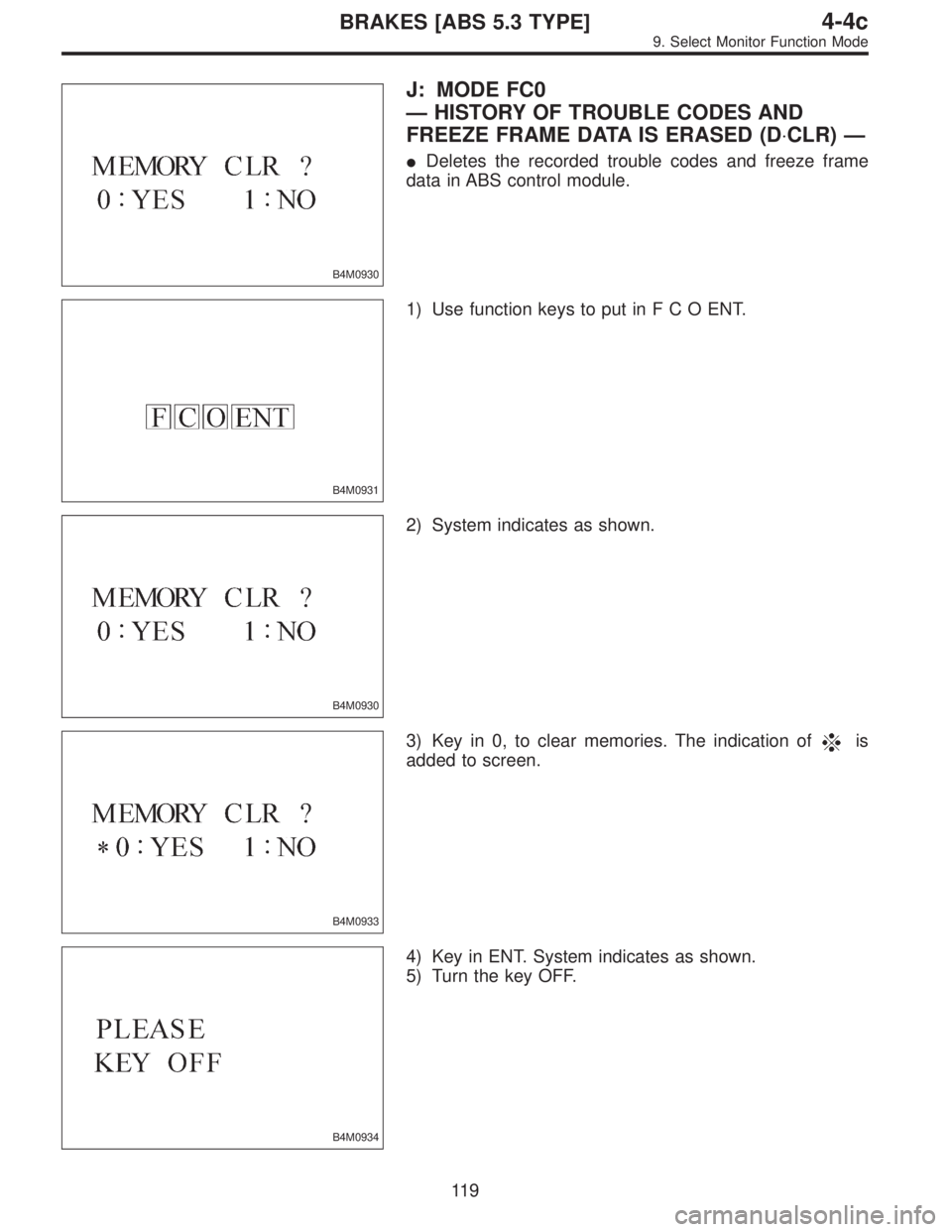
B4M0930
J: MODE FC0
—HISTORY OF TROUBLE CODES AND
FREEZE FRAME DATA IS ERASED (D⋅CLR)—
�Deletes the recorded trouble codes and freeze frame
data in ABS control module.
B4M0931
1) Use function keys to put inFCOENT.
B4M0930
2) System indicates as shown.
B4M0933
3) Key in 0, to clear memories. The indication ofis
added to screen.
B4M0934
4) Key in ENT. System indicates as shown.
5) Turn the key OFF.
11 9
4-4cBRAKES [ABS 5.3 TYPE]
9. Select Monitor Function Mode
Page 2460 of 2890
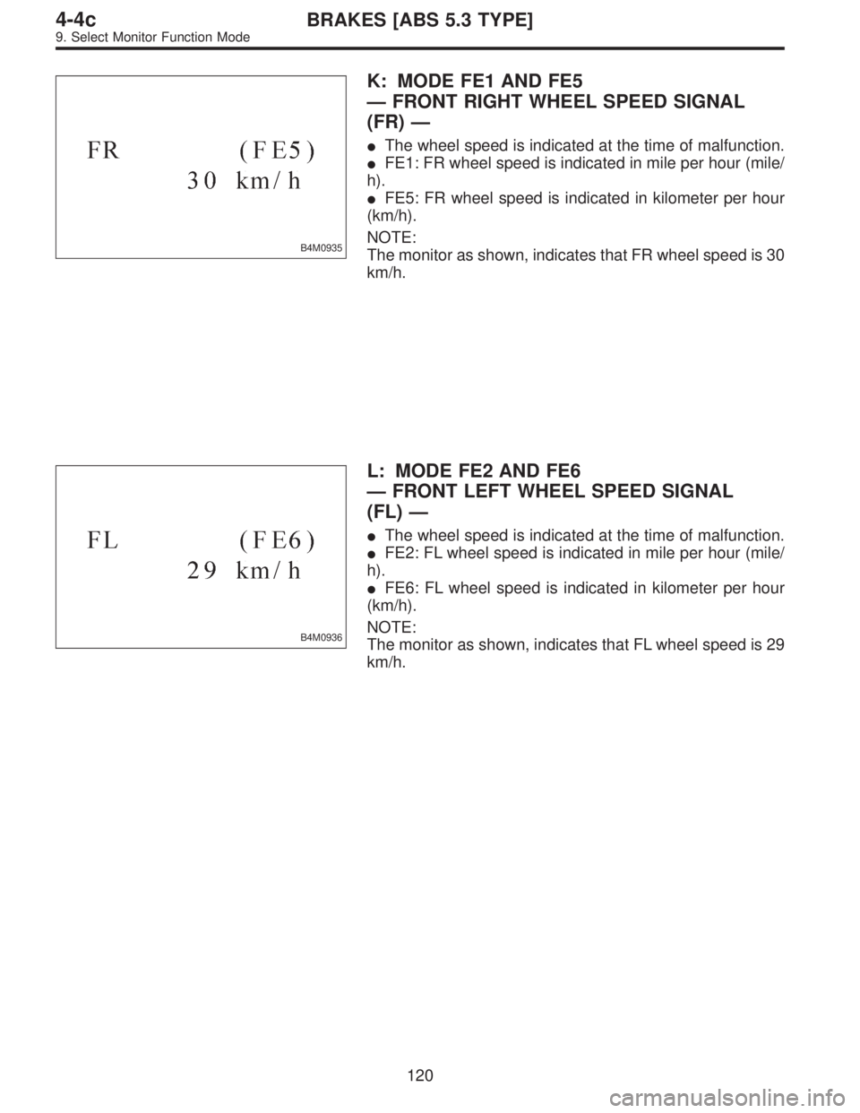
B4M0935
K: MODE FE1 AND FE5
—FRONT RIGHT WHEEL SPEED SIGNAL
(FR)—
�The wheel speed is indicated at the time of malfunction.
�FE1: FR wheel speed is indicated in mile per hour (mile/
h).
�FE5: FR wheel speed is indicated in kilometer per hour
(km/h).
NOTE:
The monitor as shown, indicates that FR wheel speed is 30
km/h.
B4M0936
L: MODE FE2 AND FE6
—FRONT LEFT WHEEL SPEED SIGNAL
(FL)—
�The wheel speed is indicated at the time of malfunction.
�FE2: FL wheel speed is indicated in mile per hour (mile/
h).
�FE6: FL wheel speed is indicated in kilometer per hour
(km/h).
NOTE:
The monitor as shown, indicates that FL wheel speed is 29
km/h.
120
4-4cBRAKES [ABS 5.3 TYPE]
9. Select Monitor Function Mode
Page 2461 of 2890
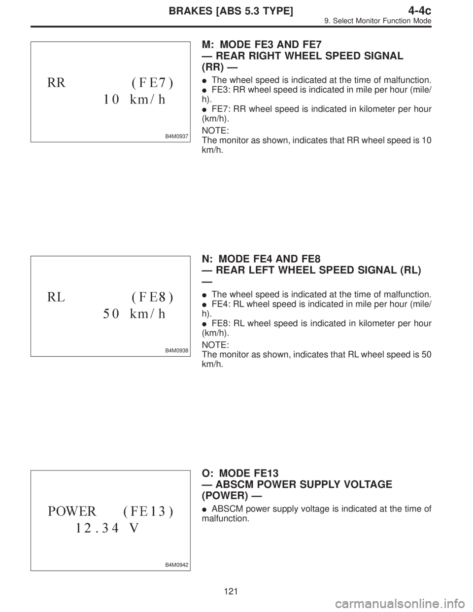
B4M0937
M: MODE FE3 AND FE7
—REAR RIGHT WHEEL SPEED SIGNAL
(RR)—
�The wheel speed is indicated at the time of malfunction.
�FE3: RR wheel speed is indicated in mile per hour (mile/
h).
�FE7: RR wheel speed is indicated in kilometer per hour
(km/h).
NOTE:
The monitor as shown, indicates that RR wheel speed is 10
km/h.
B4M0938
N: MODE FE4 AND FE8
—REAR LEFT WHEEL SPEED SIGNAL (RL)
—
�The wheel speed is indicated at the time of malfunction.
�FE4: RL wheel speed is indicated in mile per hour (mile/
h).
�FE8: RL wheel speed is indicated in kilometer per hour
(km/h).
NOTE:
The monitor as shown, indicates that RL wheel speed is 50
km/h.
B4M0942
O: MODE FE13
—ABSCM POWER SUPPLY VOLTAGE
(POWER)—
�ABSCM power supply voltage is indicated at the time of
malfunction.
121
4-4cBRAKES [ABS 5.3 TYPE]
9. Select Monitor Function Mode
Page 2462 of 2890
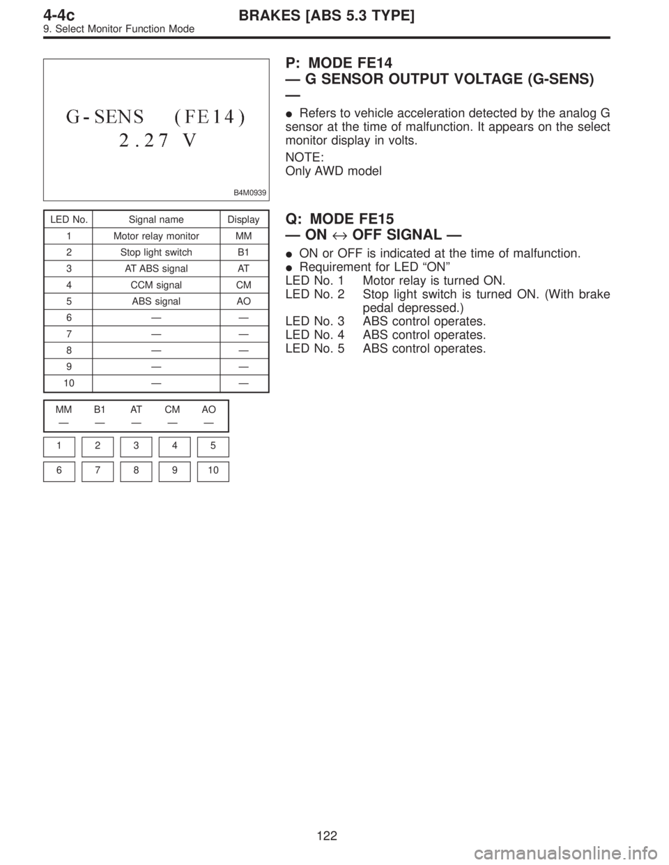
B4M0939
P: MODE FE14
—G SENSOR OUTPUT VOLTAGE (G-SENS)
—
�Refers to vehicle acceleration detected by the analog G
sensor at the time of malfunction. It appears on the select
monitor display in volts.
NOTE:
Only AWD model
LED No. Signal name Display
1 Motor relay monitor MM
2 Stop light switch B1
3 AT ABS signal AT
4 CCM signal CM
5 ABS signal AO
6——
7——
8——
9——
10——
MM B1 AT CM AO
—————
1
2345
678910
Q: MODE FE15
—ON↔OFF SIGNAL—
�ON or OFF is indicated at the time of malfunction.
�Requirement for LED“ON”
LED No. 1 Motor relay is turned ON.
LED No. 2 Stop light switch is turned ON. (With brake
pedal depressed.)
LED No. 3 ABS control operates.
LED No. 4 ABS control operates.
LED No. 5 ABS control operates.
122
4-4cBRAKES [ABS 5.3 TYPE]
9. Select Monitor Function Mode