Page 2439 of 2890
 Turn ignition switch to ON.
2) Measure voltage between ABSCM and chassis ground.
: Connector & terminal
(F49) No. 22 (+)—Chassis grou")
B4M0901A
8L16CHECK BATTERY SHORT BETWEEN
RELAY BOX AND ABSCM.
1) Turn ignition switch to ON.
2) Measure voltage between ABSCM and chassis ground.
: Connector & terminal
(F49) No. 22 (+)—Chassis ground (�)
(F49) No. 10 (+)—Chassis ground (�)
Is voltage 0 V?
: Go to next step.
: Repair harness between relay box and ABSCM.
Check fuse SBF6.
3) Turn ignition switch to OFF.
4) Measure voltage between ABSCM and chassis ground.
: Connector & terminal
(F49) No. 22 (+)—Chassis ground (�)
(F49) No. 10 (+)—Chassis ground (�)
Is voltage 0 V?
: Go to step8L17.
: Repair harness between relay box and ABSCM.
Check fuse SBF6.
B4M0902A
8L17CHECK GROUND SHORT AT ABSCM
MONITOR TERMINAL.
Measure resistance between ABSCM terminals.
: Connector & terminal
To (F49) No. 10—No. 1
Is resistance less than 0.5Ω?
: Go to step8L18.
: Replace ABSCM.
B4M0903A
8L18CHECK BATTERY SHORT AT ABSCM
MONITOR TERMINAL.
1) Disconnect connector cover from ABSCM connector.
2) Connect all connectors.
3) Turn ignition switch to ON.
4) Measure voltage between ABSCM connector terminals.
: Connector & terminal
(F49) No. 10 (+)—No.1(�)
Is voltage less than 2 V?
: Go to next step.
: Replace ABSCM.
5) Turn ignition switch to OFF.
6) Measure voltage between ABSCM connector terminals.
: Connector & terminal
(F49) No. 10 (+)—No.1(�)
Is voltage less than 2 V?
: Go to step8L19.
: Replace ABSCM.
99
4-4cBRAKES [ABS 5.3 TYPE]
8. Diagnostics Chart with Trouble Code
Page 2440 of 2890

Is the motor ground terminal tightly
clamped?
: Go to step8L20.
: Tighten the clamp of motor ground term")
B4M0808
8L19
CHECK MOTOR GROUND.
: Tightening torque:
32±10 N⋅m (3.3±1.0 kg-m, 24±7 ft-lb)
Is the motor ground terminal tightly
clamped?
: Go to step8L20.
: Tighten the clamp of motor ground terminal.
B4M0904A
8L20CHECK ABSCM MOTOR DRIVE TERMI-
NAL.
1) Measure voltage between ABSCM connector terminals.
2) Operate the check sequence.
: Connector & terminal
(F49) No. 22 (+)—No.1(�)
Does the voltage drop from 10—13Vto
less than 1.5 V, and rise to 10—13 V again
when carrying out the check sequence?
: Go to step8L21.
: Replace ABSCM.
B4M0905A
8L21
CHECK MOTOR OPERATION.
1) Measure voltage between ABSCM connector terminals.
2) Operate the check sequence.
: Connector & terminal
(F49) No. 10 (+)—No.1(�)
Does the voltage raise from less than 1.5 V
to 10—13 V, and return to less than 1.5 V
again when carrying out the check
sequence?
Can motor revolution noise (buzz) be heard
when carrying out the check sequence?
: Go to step8L22.
: Replace hydraulic unit.
100
4-4cBRAKES [ABS 5.3 TYPE]
8. Diagnostics Chart with Trouble Code
Page 2441 of 2890
8L22CHECK POOR CONTACT IN CONNEC-
TOR BETWEEN HYDRAULIC UNIT,
RELAY BOX AND ABSCM.
: Is there poor contact in connector between
hydraulic unit, relay box and ABSCM?
: Repair connector.
: Go to step8L23.
8L23
CHECK ABSCM.
1) Connect all connectors.
2) Erase the memory.
3) Perform inspection mode.
4) Read out the trouble code.
: Is the same trouble code as in the current
diagnosis still being output?
: Replace ABSCM.
: Go to next.
: Are other trouble codes being output?
: Proceed with the diagnosis corresponding to the
trouble code.
: A temporary poor contact.
101
4-4cBRAKES [ABS 5.3 TYPE]
8. Diagnostics Chart with Trouble Code
Page 2442 of 2890
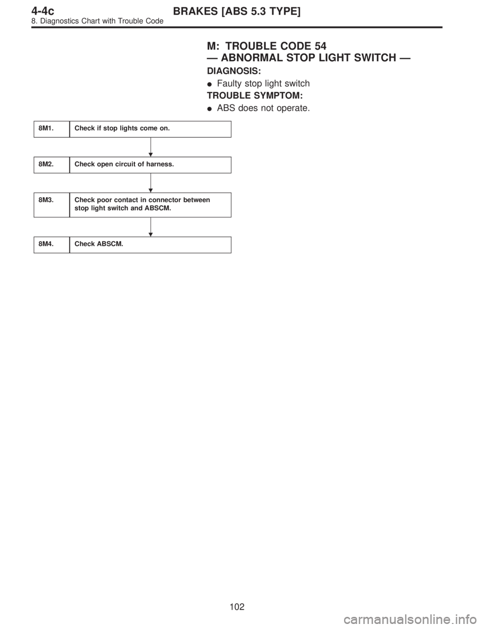
M: TROUBLE CODE 54
—ABNORMAL STOP LIGHT SWITCH—
DIAGNOSIS:
�Faulty stop light switch
TROUBLE SYMPTOM:
�ABS does not operate.
8M1.Check if stop lights come on.
8M2.Check open circuit of harness.
8M3.Check poor contact in connector between
stop light switch and ABSCM.
8M4.Check ABSCM.
�
�
�
102
4-4cBRAKES [ABS 5.3 TYPE]
8. Diagnostics Chart with Trouble Code
Page 2443 of 2890
WIRING DIAGRAM:
B4M1041
8M1
CHECK IF STOP LIGHTS COME ON.
Depress the brake pedal.
: Do stop lights turn on?
: Go to step8M2.
: Repair stop lights circuit.
103
4-4cBRAKES [ABS 5.3 TYPE]
8. Diagnostics Chart with Trouble Code
Page 2444 of 2890
B4M0908A
8M2
CHECK OPEN CIRCUIT OF HARNESS.
1) Turn ignition switch to OFF.
2) Disconnect connector from ABSCM.
3) Depress brake pedal.
4) Measure voltage between ABSCM connector and chas-
sis ground.
: Connector & terminal
(F49) No. 36—Chassis ground
Is voltage 10—13 V?
: Go to step8M3.
: Repair harness between stop light switch and
ABSCM.
8M3CHECK POOR CONTACT IN CONNEC-
TOR BETWEEN STOP LIGHT SWITCH
AND ABSCM.
: Is there poor contact in connector between
stop light switch and ABSCM?
: Repair connector.
: Go to step8M4.
8M4
CHECK ABSCM.
1) Connect all connectors.
2) Erase the memory.
3) Perform inspection mode.
4) Read out the trouble code.
: Is the same trouble code as in the current
diagnosis still being output?
: Replace ABSCM.
: Go to next.
: Are other trouble codes being output?
: Proceed with the diagnosis corresponding to the
trouble code.
: A temporary poor contact.
104
4-4cBRAKES [ABS 5.3 TYPE]
8. Diagnostics Chart with Trouble Code
Page 2445 of 2890
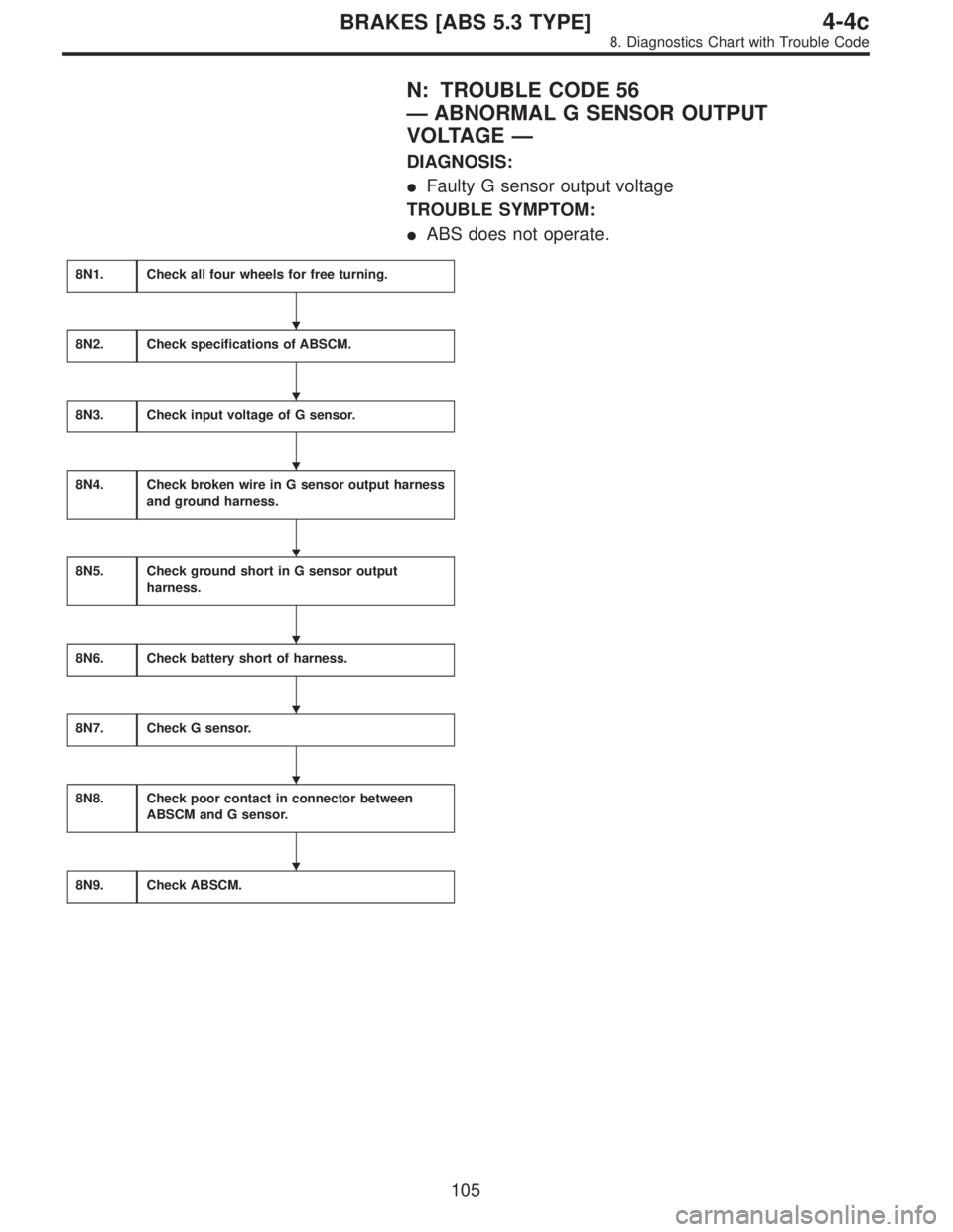
N: TROUBLE CODE 56
—ABNORMAL G SENSOR OUTPUT
VOLTAGE—
DIAGNOSIS:
�Faulty G sensor output voltage
TROUBLE SYMPTOM:
�ABS does not operate.
8N1.Check all four wheels for free turning.
8N2.Check specifications of ABSCM.
8N3.Check input voltage of G sensor.
8N4.Check broken wire in G sensor output harness
and ground harness.
8N5.Check ground short in G sensor output
harness.
8N6.Check battery short of harness.
8N7.Check G sensor.
8N8.Check poor contact in connector between
ABSCM and G sensor.
8N9.Check ABSCM.
�
�
�
�
�
�
�
�
105
4-4cBRAKES [ABS 5.3 TYPE]
8. Diagnostics Chart with Trouble Code
Page 2446 of 2890
WIRING DIAGRAM:
B4M1050
8N1CHECK ALL FOUR WHEELS FOR FREE
TURNING.
: Have the wheels been turned freely such as
when the vehicle is lifted up, or operated on
a rolling road?
: The ABS is normal. Erase the trouble code.
: Go to step8N2.
B4M0910A
8N2
CHECK SPECIFICATIONS OF ABSCM.
Check specifications of the plate attached to the ABSCM.
: Is an ABSCM for 4WD model installed on a
FWD model?
CAUTION:
Be sure to turn ignition switch to OFF when removing
ABSCM.
: Replace ABSCM.
: Go to step8N3.
106
4-4cBRAKES [ABS 5.3 TYPE]
8. Diagnostics Chart with Trouble Code

![SUBARU LEGACY 1996 Service Repair Manual WIRING DIAGRAM:
B4M1041
8M1
CHECK IF STOP LIGHTS COME ON.
Depress the brake pedal.
: Do stop lights turn on?
: Go to step8M2.
: Repair stop lights circuit.
103
4-4cBRAKES [ABS 5.3 TYPE]
8. Diagnostics](/manual-img/17/57433/w960_57433-2442.png "SUBARU LEGACY 1996 Service Repair Manual WIRING DIAGRAM:
B4M1041
8M1
CHECK IF STOP LIGHTS COME ON.
Depress the brake pedal.
: Do stop lights turn on?
: Go to step8M2.
: Repair stop lights circuit.
103
4-4cBRAKES [ABS 5.3 TYPE]
8. Diagnostics")
 Turn ignition switch to OFF.
2) Disconnect connector from ABSCM.
3) Depress brake pedal.
4) Measure voltage between ABSCM connector and chas-
sis ground.")